O que é perda de retorno?
14 de fevereiro de 2023/Geral, fundamentos de aprendizado, instalação e teste
Return loss is the ratio of signal power injected from a source compared to the amount that is returned or reflected back toward the source. It is a critical performance parameter in both copper twisted pair and fiber optic cabling systems, because it can interfere with the transmitted signal and can contribute to an increase in the measured insertion loss (the amount of power that a that a signal loses as it travels along a cable link).
If more power is reflected back to the source, less power is available at the far end of the cable. In some fiber optic systems, return loss can even damage the transceiver laser source.
The Formula for Calculating Return Loss
Measured in decibels (dB), return loss is calculated by comparing the input (or incident) power to the reflected power using the following formula:
Return Loss = 10*log (incident power/reflected power) in +dB
The result is always a positive number, and a higher value is better. (The fact that the value is expressed as positive is a requirement of both TIA and ISO standards, but can lead to confusion — learn more in Are You Positive It’s Negative?) Consider that if none of the power from the source signal was reflected back, there would be an infinite return loss. A higher return loss generally correlates with less distortion in the transmitted signal.
Return Loss vs. Reflectance
Reflectance is essentially the inverse of return loss. Rather than the amount of signal injected compared to the amount returned, reflectance is the amount of signal returned compared to the amount injected. Reflectance is also expressed in dB, but it is a negative number as shown in this formula:
Reflectance = 10*log (reflected power/incident power) in -dB
The lower the number, the better the reflectance. One way to know if high or low values are better is to remember that values further away from zero are better for both return loss and reflectance. Note that while return loss is used to test the entire fiber link, reflectance is used for individual events, i.e., connection points. (Learn more in our article about the difference between return loss and reflectance.)
Return Loss in Optical Fiber
Return loss in optical fiber cabling systems is much less than in copper. That is one of the reasons why fiber supports much greater distances. For example, typical optical return loss ranges between 20 dB and 75 dB, depending on the application and the type, wavelength, pulse width, and backscatter coefficient of the fiber under test. In comparison, the return loss limit for a Category 6 copper twisted pair cabling link is 10 dB at 250 MHz.
Individual connection points also have a reflectance value, which can be measured using an Optical Time Domain Reflectometer (OTDR). However, most manufacturers specify the reflectance of their components in Return Loss, which means that the value is expressed as a positive number. Remember, reflectance is a negative number; the lower the number, the better the overall return loss and insertion loss on a link will be. A good multimode fiber connector will have a reflectance of -35 dB or lower (or a return loss of 35 dB or greater), while a good single-mode connector will have a reflectance of -50 dB or lower. A good fusion splice will typically be much lower, and those values often can’t be measured with most field testers.
Causes of Return Loss in Optical Fiber Systems
Return loss in an optical fiber system is primarily caused by Fresnel reflections at connection points (i.e., connectors and splices). Dirty connector end faces are by far the most common cause, degrading return loss by 20 dB or more. Return loss can also be caused by poorly polished end faces, poorly mated connectors (i.e., air gaps and core misalignments), cracks in the fiber, open fiber ends, and impurities introduced into the fiber core during the manufacturing process. Micro and macro bends in the fiber that can occur as a result of installation stresses, such as exceeding bend radius or pulling tension requirements, can also affect return loss.
The angle of a connector end face can also have an impact on return loss. A UPC (ultra physical contact) connector end face is slightly rounded, while an APC (angled physical contact) end face is slanted at 8 degrees.
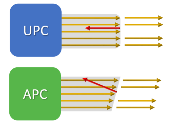
End face shapes of UPC and APC connectors
When two UPC connectors mate, reflectance is directed straight back through the fiber core toward the source. However, the angled end face of an APC connector causes much of the reflected light to angle into and be absorbed by the cladding that surrounds the fiber core. While a good UPC single-mode connector will have a value of -50 dB or lower, an APC single-mode connector is typically -60 dB or lower. APC connectivity is therefore often deployed in fiber applications that are more susceptible to reflectance. (Learn more about APC fiber connectivity.)
Return Loss Requirements
As previously mentioned, good return loss performance is also a good indication of good insertion loss performance, which is the primary parameter needed to ensure support for fiber optic applications and required for fiber attenuation (sometimes called loss or Tier 1) certification testing. Poor return loss performance can ultimately cause a fiber link to fail insertion loss and not pass certification testing.
In addition, there are some applications that are more susceptible to reflectance, where the number and return loss values of connection points can reduce maximum insertion loss requirements. This is the situation with low-cost, low-power transceivers used in newer DR and FR short-reach single-mode applications. Consequently, IEEE standards specify connection reflectance values for these applications based on the number of mated pairs in a channel. This can require reducing the number of mated pairs or the maximum allowed channel insertion loss. (Learn more about insertion loss requirements in short-reach single-mode.)
Tools for Testing Return Loss in Optical Fiber Systems
While an Optical Loss Test Set (OLTS) like the Fluke Networks CertiFiber® Pro provides low uncertainty link and channel attenuation testing, field testing for return loss in a fiber optic system requires an OTDR that can measure the amount of light reflected back to the source. This is required for projects that specify extended (sometimes called Tier 2) testing in addition to attenuation testing.
OTDRs transmit high-power light pulses into a fiber, and when these pulses of light meet reflective events (i.e., connections, breaks, cracks, splices, sharp bends, or the end of the fiber), they are reflected back, traced, and characterized by the instrument. Return loss for a link is measured by calculating the total of all light reflected from all events and the total backscatter of the link. An OTDR also provides reflectance values and the location for each individual event, which is ideal for applications like short-reach single-mode, where you need to know the specific reflectance of connections, and for troubleshooting.
It is important to note that the use of an OTDR is considered an alternative test method. It does not replace the OLTS, because the total attenuation measurement achieved with an OTDR does not necessarily depict the total loss that will occur on a link once it is live. (Find out more about using both an OLTS and an OTDR for a complete testing strategy.)
Return Loss Testing Procedure for Optical Fiber
Testing return loss with an OTDR requires the use of launch and tail cords, which allow for measuring the reflectance of the first and last connector so they can be included in the overall return loss measurement. The lengths of the launch fiber and tail cord also need to be removed from the measurement via compensation. OTDRs like the OptiFiber™ Pro are easy to set up by simply selecting the fiber type and test limits, then setting the launch compensation.
When using an OTDR, testing is done bidirectionally since the reflectance of specific connectors and splices depends on the test direction. Even if two connected fibers are of the same type, the fibers may have slight variations and different backscatter coefficients that can cause more light to be reflected after a connection than before a connection.
An OTDR plots reflected and backscattered light in a trace that graphically displays the characterization of a fiber link. Experienced OTDR users can typically recognize reflective events for launch cords, connectors, mechanical splices, fusion splices, mis-matched fibers, and the end of the link. However, not everyone is a trace analysis expert. The OptiFiber Pro features advanced logic that automatically interprets the trace and provides an ”EventMap” that indicates the location and reflectance of connectors, splices, and anomalies. (Learn more about fiber troubleshooting, including OTDR’s, in our Fiber Troubleshooting white paper.)
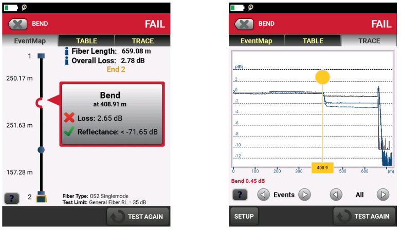
Examples of an EventMap and a trace of OTDR results on an OptiFiber tool
Return Loss in Copper
Return loss is also a performance parameter for copper twisted pair cabling systems. A key difference is the fact that return loss over copper varies with the frequency of the signal — it is essentially considered a noise measurement and is therefore worse at higher frequencies. For example, the maximum allowed return loss for Category 5e specified to 100 MHz is around 16 dB, while Category 6A specified to 500 MHz is just 8 dB. Remember, the higher the number, the better the return loss. In copper cabling, too much return loss can increase crosstalk, distort signals, and result in higher bit error rates.
Causes of Return Loss in Copper Cabling Systems
Return loss in copper cabling links is caused by impedance mismatches that can occur between components, or by minor impedance variations along a cable’s length. That is why connectivity manufacturers strive to design their plugs and jacks to have matched impedance, while cable manufacturers strive to measure and control uniformity throughout the manufacturing process. Return loss can also be caused by kinked or damaged cables or by poor termination practices, such as additional unnecessary pair untwist at termination points. Another potential cause of return loss in copper cabling is water in the cable.
How to Test Return Loss in Copper Cabling Systems
Because return loss changes with frequency, it is tested over the entire frequency range for a given application. For example, in a Category 5e channel, return loss is tested from 1 MHz to 100 MHz. For Category 6A, it is tested from 1 MHz to 500 MHz. The Fluke Networks DSX CableAnalyzer™ series of testers automatically tests each pair at each frequency, based on the application being tested, and plots results over the entire frequency as shown below.
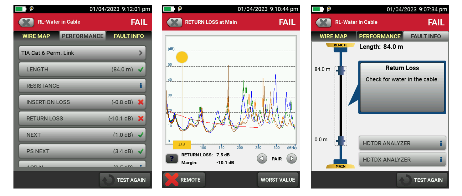
Examples of results from copper cable testing displayed on a DSX CableAnalyzer showing a return loss failure (left), a frequency plot of the return loss (center), and the “Fault Info” screen diagnosing the cause of the return loss failure.
When return loss happens at a single frequency point and all other frequencies are passing with margin, that is typically an indication of a cable issue. Generally, when all four pairs are failing (particularly at lower frequencies), it can indicate a low-quality cable or water in the cable. Interpreting frequency plots of return loss failures requires significant expertise — but that ability is incorporated into the “Fault Info” feature in the DSX CableAnalyzer. (Learn more about how to measure and test return loss in copper systems.)
What Makes Good Return Loss Testing Equipment?
Whether you are testing fiber or copper, the key to a good return loss tester is accuracy.
For fiber certification testing, you need a tester that supports OTDR testing with the ability to test multimode and single-mode fiber links at multiple wavelengths and to industry standards or custom test limits. Additionally, the ability to set up a tester easily and automatically interpret the OTDR trace with a graphical map showing the location of reflection events can go a long way toward smoother troubleshooting. As part of the modular Versiv™ cabling certification product family, OptiFiber™ Pro is a highly accurate OTDR that provides usability without cumbersome and complicated features for enterprise network engineers and cable installers in both enterprise and OSP environments. OptiFiber Pro supports LinkWare™ Live cloud-based results management, can easily be updated with the latest firmware to support new applications, and is backed by a comprehensive protection plan with 24x7 technical support.
For copper certification testing, it is important to select a tester that is independently certified by a technically qualified laboratory to meet the TIA and IEC accuracy requirements for the cabling you expect to test. For example, Level IIIe accuracy is required for TIA Category 6A / IEC Class EA testers. For maximum flexibility and to ensure highly accurate measurements, choose a tester with TIA Level 2G or IEC Level VI accuracy. The tester should have the ability to certify the performance of all categories of cable and current applications. It should show results for all parameters on all four pairs of a cable, including return loss. (It’s also worth remembering that Alien Crosstalk is part of the standard, so having a tester that measures it is invaluable in those occasional instances where it is required.) Finally, a tester with diagnostic capabilities can reduce the time required to fix the causes of return loss. The DSX CableAnalyzer series of copper certification testers meet all of these requirements —and as part of the Versiv platform (like OptiFiber Pro), supports LinkWare Live, can update firmware easily, and is backed by comprehensive Fluke Networks protection.
If your team works with both fiber and copper cabling, look for a tester that can perform both types of testing through the same user interface, which can greatly reduce both learning time and the potential for mistakes. Reporting and archival software that supports copper and fiber results will save even more time — and Versiv meets these requirements as well, with a single user interface for copper certification and both OLTS and OTDR testing (and even end face inspection). Versiv allows all four test types to be specified as part of a single project, ensuring that tests are not skipped by mistake. And for reporting, LinkWare provides a single platform for all these tests on both PC- and cloud-based versions.
Continuar lendo
- Reflectance and Optical Return Loss (ORL) Measurement and Testing with OptiFiber
- Certificação e testes de fibra: Tudo o que você realmente precisa é perda, comprimento (e, às vezes, refletância)
- Short-Reach Single-Mode Puts Reflectance on the Radar
- Você tem certeza de que é negativo?
- Connector Loss, Return Loss, and Reflectance — “Highs and Lows”
Publicações recentes Ver tudo >
Mais publicações gerais Ver tudo >
Explore nossos Produtos
Certificadores de cabos de cobre DSX CableAnalyzer™ Series
CertiFiber® Pro Optical Loss Test Set
Família OTDR OptiFiber® Pro


©2006-2021 Fluke Corporation。保留所有权利。
RM2011, 20/F, SCITECH Tower, 22 Jianguomenwai Avenue, Chaoyang District, Beijing, China
地址:北京市朝阳区建国门外大街22号赛特大厦20层2011室
联系电话:400-8103435
沪ICP备11037028号-15![]()