OTDR: Sua melhor solução de problemas
28 de fevereiro de 2018 / Informações Gerais
So you’ve finished your fiber cable installation and are now on to the task of certifying the cable plant using an optical loss test set (OLTS) – it’s the tool you need for Tier 1 certification and the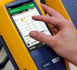 most accurate for measuring loss to ensure application support.
Unfortunately, you find some critical fiber links that far exceed your loss budget for the application. You now need to troubleshoot those links so you can fix the problems and move on to your next job. And the faster you can locate the problems, the faster you can fix them.
Your OLTS can’t tell you exactly where the loss is happening along the link, and you simply don’t have the time to inspect each failed links’ connectors for contamination or try to visually locate a potential break (which could be anywhere) using a visual fault locator (VFL). But if you’ve got an optical time domain reflectometer (OTDR), you can rest assured. It is, after all, the ultimate troubleshooting tool.
Reflections Tell You More
Problems with your fiber links can be caused by microbends, kinks and breaks somewhere along the fiber, contaminated connectors, faulty fusion splices and a variety of other field termination, cable management or installation mishaps. Thankfully your OTDR has the ability to detect reflected light, or backscatter, to locate and measure the loss of any of these events. Access to this level of detail with an OTDR also arms you with a complete picture of the fiber installation and the overall quality of the workmanship.
Even if the application will only use the lower wavelength for transmission, when troubleshooting with your OTDR, it’s best to test at both the 850 and 1300nm for multimode and 1310 and 1550 for singlemode. Normally, the higher wavelength would show a lower loss, but if the fiber is stressed, the higher wavelength will show significantly higher loss, and the problem will be easier to detect.
It’s also important to troubleshoot in both directions. A mismatched splice could look like a gainer (i.e., negative loss) in one direction and show too much loss (i.e., false loss) in the other direction. But if you do a bidirectional test that averages the loss (as required in Tier 2 testing), you’ll get the actual loss. Thankfully, Fluke Networks’ OptiFiber® Pro features a built-in SmartLoop Assistant that makes bidirectional testing easy.
Tudo se resume ao traçado
Ao executar uma solução de problemas com um OTDR, você obtém uma assinatura gráfica da atenuação em uma fibra ao longo do seu comprimento. Embora um traço de OTDR possa parecer um pouco complexo, ele conta a história do link de fibra que está em teste, com picos e vales revelando o tipo de evento.
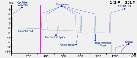
Experienced OTDR users will recognize reflective events for tester connectors, launch cords, connectors, mechanical splices, fusion splices, miss-matched fibers and the end of the link. E eles sabem que os pequenos sinais sonoros que perceberem após o término do link são fantasmas, eles não são eventos reais com os quais precisam se preocupar.
Mas se você não for um expert em análise de traços, não e preocupe. The OptiFiber® Pro also uses advanced logic to interpret the trace and provide an EventMap that characterizes the actual events. E os eventos de falhas são destacados em ícones vermelhos para que você possa localizar o seu problema ainda mais rápido.
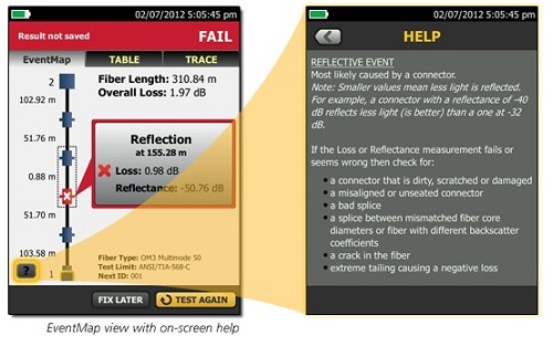
Acessível a partir do ícone de ajuda na parte inferior esquerda do EventMap, O OptiFiber Pro inclusive sugere medidas corretivas para resolver qualquer problema. Now that definitely makes for an ultimate troubleshooting tool!

