Inspeções mais fáceis de terminações de fibras: Principais mudanças na IEC 61300-3-35
30 de abril de 2025/Geral, instalação e teste, atualização e resolução de problemas
É crucial inspecionar, limpar e reinspecionar as terminações de fibra antes de conectar os conectores, seja em cabos de manobra e troncos dentro da rede ou no cabo de referência de teste conectado ao testador. Terminações de fibra contaminadas podem causar perda de sinal e reflexos que degradam o desempenho de rede. Elas também podem transferir sujeira para portas limpas, incluindo aquelas em equipamentos de rede caros.
A Comissão Eletrotécnica Internacional (International Electrotechnical Commission, IEC) desenvolveu a norma 61300-3-35 para orientar a inspeção consistente de terminações de fibra. Aqui, discutimos a edição mais recente, que tem algumas mudanças significativas que podem simplificar seu fluxo de trabalho de inspeção e limpeza.

O que é a norma IEC 61300-3-35?
A norma IEC 61300-3-35 concentra-se na observação e classificação de detritos, arranhões e defeitos durante a inspeção visual das terminações de fibra. Ela define critérios de conformidade microscópica mínima, procedimentos de inspeção e medidas quantitativas para analisar imagens de terminações.
Como todas as normas, a norma 61300-3-35 passa por revisões e atualizações. A primeira edição da 2009 introduziu métodos para avaliar quantitativamente a qualidade da terminação de fibra e determinar defeitos de superfície permitidos (arranhões, furos e detritos) que podem afetar o desempenho óptico. A segunda edição em 2015 (61300-3-35:2015) introduziu critérios específicos para a classificação da limpeza com base na qualidade e tamanho dos arranhões (características de superfície permanentes) e defeitos (partículas e detritos) em quatro zonas diferentes (regiões) de uma terminação de fibra: Zona A (núcleo), Zona B (revestimento), Zona C (adesivo) e Zona D (contato/virola). O núcleo da fibra, para onde o sinal viaja, tem os requisitos mais rigorosos.
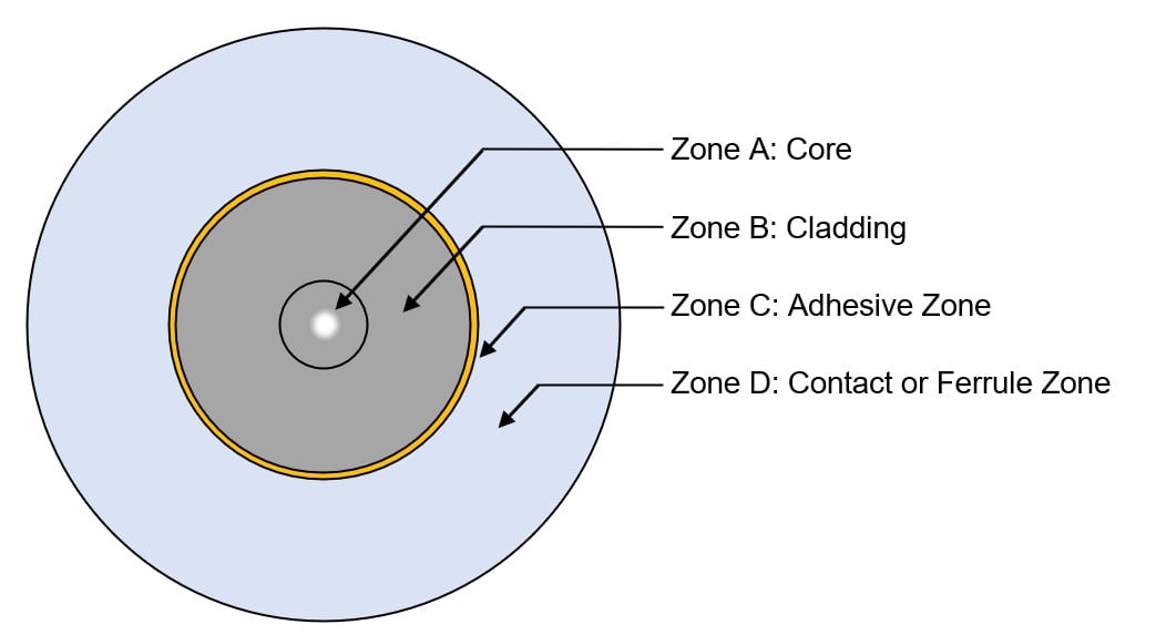
A norma IEC 61300-3-35:2015 avalia a limpeza da fibra de acordo com a qualidade e tamanho dos arranhões e defeitos em quatro zonas diferentes da terminação.
Os critérios de limpeza descritos na IEC 61300-3-35:2015 variaram com base no tipo de conector e no tamanho da fibra. Para terminações de fibra monomodo com núcleos menores, a norma proibiu qualquer arranhão ou defeito dentro da zona do núcleo. As terminações de fibra multimodo com núcleos maiores podem ter arranhões menores ou iguais a 3 mícrons (mm) e até quatro defeitos menores ou iguais a 5 mm.
Embora esses critérios tenham fornecido consistência na avaliação da limpeza da fibra, a contagem e medição manual de arranhões e defeitos em cada zona usando um microscópio é demorada e suscetível a erros humanos. Soluções automatizadas como a Câmera FI-3000 / FI2-7300 FiberInspector™ Ultra e o FI-7000 FiberInspector™ Pro da Fluke Networks usam um processo algorítmico que classifica e certifica as terminações de fibra com base nos critérios IEC 61300-3-35, fornecendo resultados automáticos de APROVADO/REPROVADO.
O que mudou com a IEC 61300-3-35 Terceira Edição?
As principais alterações na terceira e última edição da norma, IEC 61300-3-35:2022, incluem a remoção da Zona C (adesivo) e da Zona D (contato) dos critérios APROVADO/REPROVADO. Este é um ajuste lógico, pois a contaminação nessas áreas geralmente não impede a transmissão do sinal luminoso através do núcleo do conector. A norma agora recomenda inspecionar inicialmente toda a Zona D (área de contato) e tentar remover partículas soltas que possam migrar para as Zonas A e B mais críticas (núcleo e revestimento). Se várias tentativas de limpar a zona de contato não forem bem-sucedidas, as partículas são consideradas defeitos incorporados e consideradas aceitáveis. A inspeção pode então prosseguir para as Zonas A e B, que ainda têm critérios de APROVAÇÃO/REPROVAÇÃO com base no tamanho e número dos arranhões e defeitos.
Para conectores de matriz retangular (como conectores de pressão multifibra ou MPOs), a IEC 61300-3-35:2022 recomenda inspecionar toda a virola e tentar remover partículas soltas antes de inspecionar as Zonas A e B em terminações individuais. Os MPOs apresentam uma superfície muito maior, e partículas soltas em qualquer lugar na virola podem migrar para terminações individuais da fibra, causando lacunas de ar que podem aumentar a perda de inserção e perda de retorno. Se várias tentativas de limpar a virola não forem bem-sucedidas, essas partículas também são consideradas defeitos incorporados e aceitáveis.
Para inspecionar toda a virola em busca de MPOs, a IEC 61300-3-35 permite microscópios com um campo de visão grande (LFOV) de pelo menos 6,4 x 2,5 mm e a capacidade de detectar detritos de 10mm de diâmetro. Microscópios com um pequeno campo de visão (SFOV) de pelo menos 250 μm e a capacidade de detectar defeitos de 2 μm de diâmetro e arranhões de 3 μm de largura ainda são necessários para inspecionar a zona de contato nos conectores de fibra única e as zonas de núcleo e revestimento em todas as terminações.
Os critérios específicos para as Zonas A e B também são um pouco menos rigorosos e mais bem definidos na IEC 61300-3-35:2022. Como mostrado na tabela abaixo para terminações de fibra multimodo, a edição anterior não permitia nenhum arranhão dentro da Zona A maior que 3mm, enquanto a edição mais recente agora permite quatro arranhões iguais ou menores que 4 mm e nenhum maior que 5 mm. O tamanho geral da zona de revestimento também foi ligeiramente reduzido na última edição, uma vez que os contaminantes na borda do revestimento não afetam significativamente o sinal luminoso.
|
Critérios de inspeção de terminação de fibra multimodo da norma IEC 61300-3 |
|||||
|
Zona |
Defeitos |
Arranhados |
|||
|
Edição 2, 2015 |
Edição 3, 2022 |
Edição 2, 2015 |
Edição 3, 2022 |
||
|
A: Núcleo |
4 ≤ 5 µm |
Sem limite < 2 µm 4 de 2 a 5 μm Nenhum > 5 µm |
Sem limite ≤ 3 µm |
Sem limite < 3 µm
4 ≤ 4 µm |
|
|
B: Revestimento |
Sem limite < 2 µm |
Sem limite ≤ 25 µm Nenhum > 25 µm |
Sem limite ≤ 5 µm |
Sem limite |
|
|
C: Adesivo |
Sem limite |
Sem limite |
Sem limite |
Sem limite |
|
|
D: Contato |
Nenhum ≥ 10 μm μm |
Sem limite |
Sem limite |
Sem limite |
|
A alteração mais notável na IEC 61300-3-35:2022 é a linguagem que permite que um conector cujos detritos soltos foram removidos, mas que falhou na inspeção, ainda seja usado se for aprovado nos testes de desempenho óptico para perda de inserção e perda de retorno. Em outras palavras, o desempenho óptico de um conector agora tem precedência sobre uma inspeção com falha.
Por que a IEC 61300-3-35 mudou?
As mudanças na IEC 61300-3-35:2022 foram implementadas para fornecer um método de inspeção recomendado para conectores MPO, simplificar o fluxo de trabalho de inspeção e limpeza e ajudar a evitar a substituição desnecessária e cara de cabos e/ou equipamentos.
Um dos desafios das edições anteriores era que os técnicos podiam ficar presos em um ciclo aparentemente interminável de inspeção, limpeza e reinspeção, mesmo que a contaminação estivesse apenas na área de contato. Com um fluxo de trabalho simplificado, os técnicos podem inspecionar toda a virola ou área de contato, tentar remover os detritos soltos e, em seguida, proceder à inspeção apenas das zonas críticas A e B (núcleo e revestimento).
Além disso, a presença de um defeito ou arranhão em uma terminação da fibra não significa necessariamente que ela obstrua o sinal luminoso suficientemente para afetar negativamente o desempenho. Com requisitos menos rigorosos e o desempenho óptico (perda de inserção e perda de retorno) agora tendo precedência, não há necessidade de substituir cabos e/ou equipamentos se o link estiver funcionando como esperado. As mudanças também aumentam a repetibilidade do equipamento de teste de inspeção e ajudam a evitar falhas falsas.
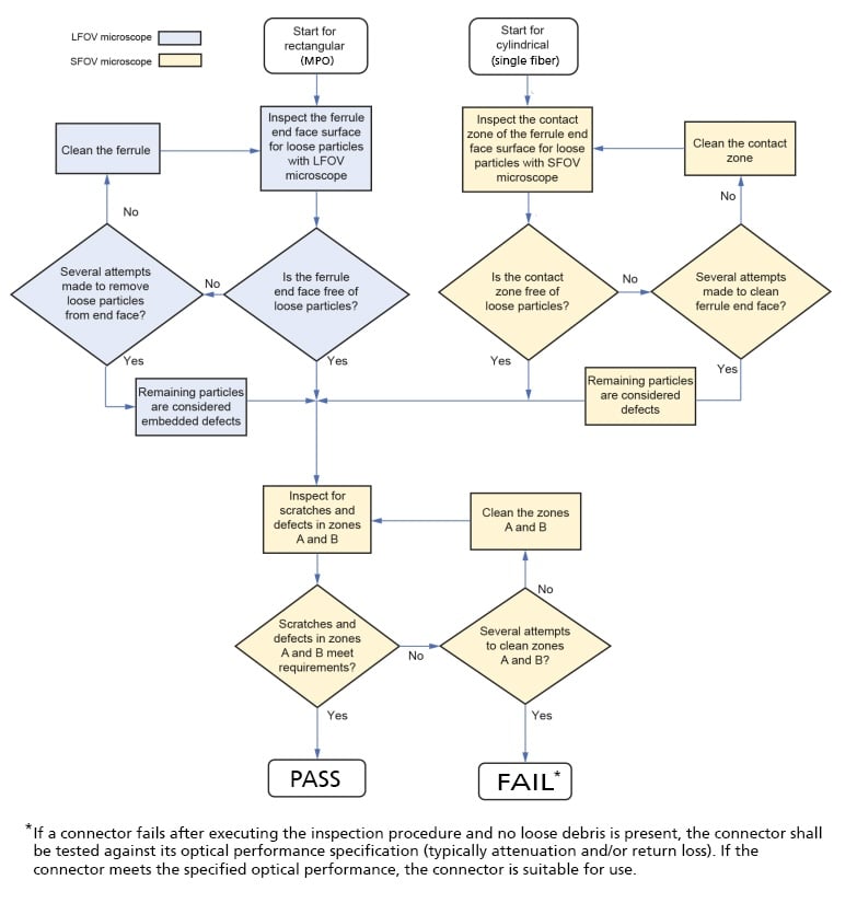
A IEC 61300-3-35:2022 simplifica o processo de inspeção e limpeza da terminação da fibra. Fonte: Comissão Eletrotécnica Internacional, da norma IEC 61300-3-35:2022.
O que as mudanças na IEC 61300-3-35 significam para você?
Essas mudanças na IEC 61300-3-35 devem simplificar seu processo de inspeção e limpeza, ajudando-o a economizar tempo e dinheiro evitando um ciclo interminável de "inspecionar, limpar e inspecionar" e reduzindo a necessidade de substituir conectores, cabos de manobra, equipamentos e outros componentes por terminações de fibra.
Você também não precisa se preocupar demais com essas mudanças. As ferramentas de inspeção de fibra da Fluke Networks foram todas atualizadas para fornecer APROVAÇÃO/REPROVAÇÃO automatizada com base na última edição da IEC 61300-3-35. Além disso, um teste de desempenho aprovado com seu testador de certificação de fibra terá precedência sobre quaisquer resultados de inspeção. No entanto, uma inspeção reprovada será indicada nos resultados do teste, o que pode ajudar na resolução de problemas futuros.
Embora a inspeção tenha se tornado mais fácil e alguns dos requisitos sejam menos rigorosos, continua sendo crucial inspecionar cada terminação de fibra de acordo com o processo recomendado e limpá-las, se necessário. Os kits de limpeza Fiber Optic Cleaning Kits da Fluke Networks contêm tudo o que você precisa para uma limpeza ideal a seco e a úmido, incluindo ferramentas Quick Clean™ para vários tipos de conectores, caneta solvente para fibra óptica com solução de limpeza de fibra especialmente formulada e cubo/cartão de limpeza conveniente.
Continue aprendendo
Publicações recentes Ver tudo >
Perda por inserção vs. Perda de retorno
14-8-2024
Mais publicações gerais Ver tudo >
Explore nossos Produtos

Câmera FI-3000 / FI2-7300 FiberInspector™ Ultra
FI-7000 FiberInspector™ Pro

Fiber Optic Cleaning Kits


©2006-2021 Fluke Corporation。保留所有权利。
RM2011, 20/F, SCITECH Tower, 22 Jianguomenwai Avenue, Chaoyang District, Beijing, China
地址:北京市朝阳区建国门外大街22号赛特大厦20层2011室
联系电话:400-8103435
沪ICP备11037028号-15![]()