O que deu errado com a perda de inserção?
30 de janeiro de 2020 / General, 101 learning, Installation and testing, Upgrading and troubleshooting, Best Practices
Have you ever carefully calculated insertion loss during the design phase and then passed your permanent link testing after installation only to find out that the channel isn’t performing once it went live?

By now you should know that your loss budget is based on the application and calculated by adding up the loss of all the components in the channel, with some margin to account for loss of power over time due to transmitter age or dirty connections (read the blog). And hopefully you understand the difference between permanent link and channel testing (read the blog).
But what you don’t always know is what will happen that can impact loss after you’ve installed, tested and certified a permanent link. That’s why it’s imperative to record and document how you calculated loss and the final permanent link test results, and to know what can add loss and impact performance after installation and testing are done.
A Quick Refresher
When it comes to calculating your loss budget during the design phase, you first need to know the loss limits for the given application as specified by IEEE standards. You then need to account for all the components in a link, including fiber, connectors, splicing, splitters and couplers. For connectors, this means including the loss specified by the manufacturer (typically 0,2 to 0.5dB). For splitters, the loss will vary based on the number of outputs. For example, a 1:16 splitter has a typical loss of 12dB per port, while a 1:32 splitter has a typically loss of 15dB per port). For splices, the loss can be as low as 0.1dB, but the maximum of 0.3dB per industry is a good value to use when calculating since the quality of the splice can vary based on the expertise of the technician.
Since insertion loss is directly related to length, the length of any cable in your link also needs to be included in the budget. For example, if the loss of your OM4 laser-optimized multimode cable is 3dB/km at the 850nm wavelength, this translates to 0.003dB per meter. Portanto, se o comprimento do seu cabo for de 50 metros, sua perda será de aproximadamente 0,15 dB, enquanto em 100 metros, sua perda será de 0,3 dB.
O equipamento ativo também precisa ser considerado de acordo com as especificações do fabricante, com base em qualquer diferença entre transmissores e receptores, além de alguma margem para considerar a perda de energia ao longo do tempo que pode ocorrer devido à idade do transmissor.
Once you’ve calculated the loss and are ready to test using either a light source and power meter such as your Fluke Networks’ SimpliFiber® Pro or optical loss test set (OLTS) such as your Fluke Networks’ CertiFiber® Pro, you need to understand what you’re testing – the entire end-to-end channel or the permanent link. While some may prefer channel testing because it’s easier to pass, it’s the permanent link you should be testing as it’s the true foundation of the network. Patch cords and equipment are often moved around, so if you test the channel, you may be missing problems with the foundation that may go undetected.
What Can Happen Next?
If you properly calculated and then tested the permanent link, and it passed, one might assume that the channel is good to go. But what if the customer decides to migrate to a higher speed, like going from 10 Gig to 40 Gig? Or what if they add in extra connections by implementing a cross connect? Or what if they eliminate an intermediate switch and join two permanent links together into one longer link? Or what if they’ve failed to keep fiber endfaces clean during moves, adds and changes? This is where it can all go wrong after you’ve already installed and tested the link.
First of all, different applications have different loss limits. If your customer is planning to migrate any link to a higher speed that has more stringent loss limits, it’s the higher speed limits that need to be considered for your calculation during the design phase. There is always the chance that a customer who claims they have no plans to migrate to higher speed ends up changing their minds. For example, if you design a system to run 10 Gig over multimode (10GBASE-SR), the maximum channel insertion loss is 2.9dB over 400 meters of OM4 multimode. But if the customer decides to upgrade to a 40 Gig multimode system (40GBASE-SR4), the maximum channel insertion loss is 1.5dB over 150 meters of OM4. It’s easy to see how an unplanned upgrade could cause problems if the system was designed and implemented for only 10 Gig. That’s why it’s imperative that you and your customers agree ahead of time on exactly which application will used to determine the loss budget – both now and in the future.
Now let’s say your customer decides that for management purposes, they want to add in another patch panel to deploy a cross connect at the switch location. If they do this after you’ve already calculated, installed and tested the link with just an interconnect, they are essentially adding in another connection point and additional loss. While this may seem like a minor change, when we’re talking about stringent insertion loss limits, the addition of a 0.2dB for another connection can push you over the limit and cause performance issues.
While it might seem that two permanent links that passed insertion loss testing can be connected and pass, this is not necessarily the case. Let’s say you install and test a permanent link in the data center from the patch panel at the core switch to the patch panel at the intermediate switch and another permanent link from there to a patch panel at the access switch in the server cabinet. If the intermediate switch is eliminated and the two permanent links become one, this adds another connection point and cable length that can also push you over the limit.
And then there’s fiber endface cleanliness. If your customer has a lot of moves, adds and changes or tampers with fiber ports and does not properly clean and inspect the endfaces, what may have been clean at the time of installation may now be dirty and adding loss to the channel.
Your Best Bet
Of course you want your customer to be happy and end up with a high-performance network – but certainly not at the expense of unanticipated reworks.
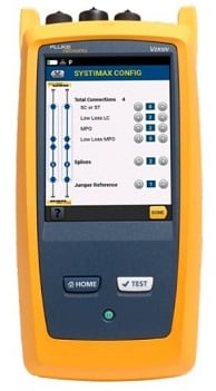
When it comes to calculating loss budgets, all you need to know is the application (both planned and future), the fiber length, number of connections, the specific vendor’s specified loss for components and a little bit of basic math. Your cabling vendor might also offer a loss calculator for their components. In fact, Fluke Networks’ CertiFiber® Pro OLTS (part of the Versiv™ Cabling Certification System) and LinkWare™ Live cloud service even incorporates CommScope’s SYSTIMAX® link loss calculator for their low and ultra-low loss fiber components right into the tester.
Once the cabling plant is installed and tested for insertion loss, make sure your customer knows exactly what was tested, the results, the margin and the impact of migrating to higher speeds, adding connection points or ending up with dirty endfaces in the future. And make sure you document it all in case something changes and your customer claims that something went wrong with the installation and insertion loss testing – certifying a cabling installation doesn’t mean anything without the burden of proof. The best way to document your results (and the test parameters you used) is to upload, manage and archive your test results with a service like LinkWare™ Live.
Publicações recentes Ver tudo >
Perda por inserção vs. Perda de retorno
14-8-2024
Mais publicações gerais Ver tudo >
Explore nossos Produtos
Certificadores de cabos de cobre DSX CableAnalyzer™ Series
CertiFiber® Pro Optical Loss Test Set


