Como testar um transceptor SFP e um cabo de rede
21 de janeiro de 2022 / Geral, fundamentos de aprendizado, instalação e teste
Recently we have been getting questions about how to determine if an SFP (Small Form-factor Pluggable) transceiver is working. We refer to SFP generically here to represent a multitude of the various optical modules that are available. Fluke Networks fiber testers can be used to measure the light that is being put out by an SFP.
How to Test an SFP Transceiver with FiberLert™ Live Fiber Detector
The simplest way to test an SFP transceiver is with the FiberLert™ live fiber detector, which lights up and beeps when placed in front of an active fiber or port. This inexpensive, pocket-sized SFP tester tests single-mode, multimode UPC and APC patch cords and transceiver ports using a “non-contact” / non-contaminating detector. By checking the cables and the SFP ports, the problem can quickly be isolated to the transceiver or the cable, as demonstrated in this video.
Checking an SFP with an Optical Power Meter
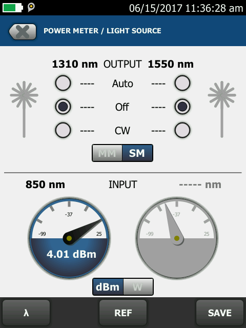
To start, put your CertiFiber™ Pro into “Power Meter” mode. From the home screen, select the TOOLS menu; if your CertiFiber module is attached, the second option will be POWER METER. Selecting that takes you directly to the power meter. It is on and running — you don’t even need to push TEST!
There are some minimal configurations to apply. We are going to focus on the bottom half of the power meter. The top is used for transmitting, but we don’t need that to test the SFP. All we are looking for is the absolute power coming out. We suggest reading this in dBm, which reflects the specifications of many SFP modules.

Readout in dBm reflects specifications of many SFP modules
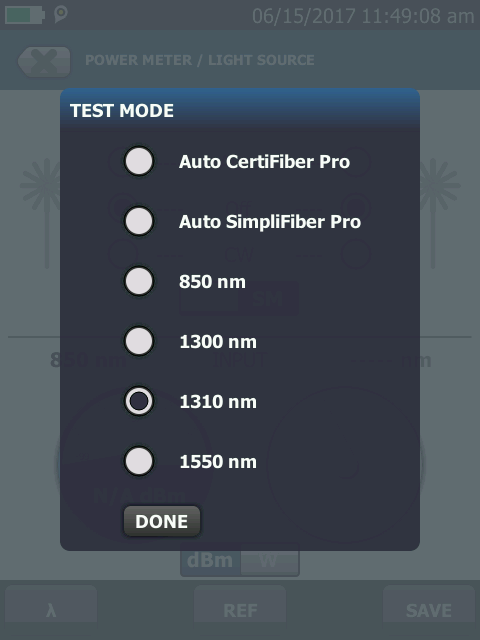
The configuration that is important is the λ (Lambda) or wavelength, in the bottom left corner. What are you testing? If it is Multimode, use 850 nm; if Singlemode, use 1310 nm. Pressing the Lambda key will give you a menu to choose appropriate wavelength.

If testing multimode, use 850; if testing singlemode, use 1310.
Consult the manufacturer’s directions regarding acceptable power levels for your meter. If you are getting a positive number, you may need to put an attenuator on your system.
What about inspection? Inspection does not work well with the SFP modules. The inspection microscopes and the related standards, such as the IEC 61300-3-35, are designed for connectors, not the output port of an SFP. The input port of an SFP should have some type of non-contact large area input port. The fiber doesn’t make physical contact with the port, so it should remain fairly clean. Even if dust or other debris has collected on the port, it may be hard to visualize with a microscope.
Testing with Multi-Fiber Links
If you are using a QSFP to transmit 40 Gig through an MPO connector, you can test it with two simple options. One would be to use a fan out cable that goes from an MPO port to multiple legs of LC connectors, then plug it into the CertiFiber Pro.
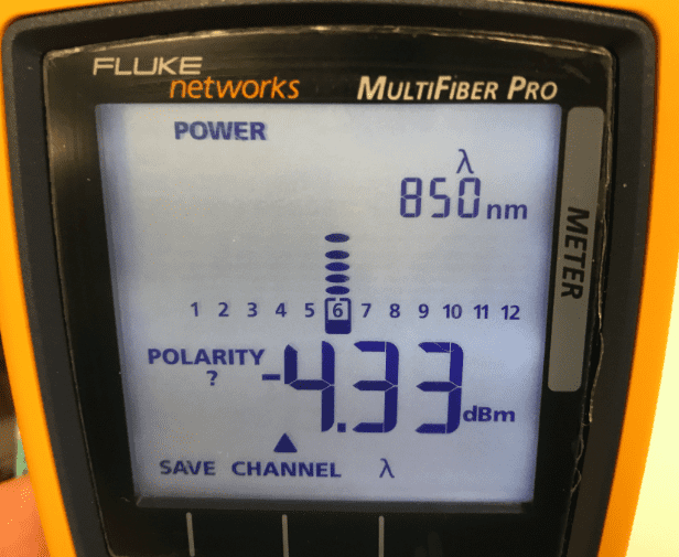
The other test option would be to plug the MPO cable directly into a MultiFiber™ Pro. Set it to POWER mode, and you can see the power level for each individual fiber. Here is an example with just one channel receiving light:

Fluke MultiFiber Pro screen configured to Power mode
Remember, if you are working with 40 Gig, you are probably only using 4 fibers. Don’t be surprised if you only see a power level on only the first or last 4 fibers in the power meter.


