Considerações para o uso de cabo híbrido de cobre-fibra
12 de janeiro de 2021 / General, Installation and testing, Upgrading and troubleshooting, Best Practices
In a previous blog, we covered what to do when you need to connect a device that is located beyond the 100-meter distance requirement and described four ways to address the problem—a new TR, the use of an extender device, extended-reach copper cable and fiber.
When using fiber to go beyond the 100m distance, devices that do not include a fiber input/output require some form of media conversion, and if that device also needs power over Ethernet (PoE), it takes a PoE media converter. Devices that include a fiber connection and power terminals for DC power can connect via hybrid copper-fiber cable, sometimes referred to as composite cable. This does of course require the use of fiber transceivers for data transmission and a power source capable of delivering low-voltage DC power over the copper conductors.
With hybrid copper-fiber cabling becoming increasingly popular for extended-distance applications, we thought it warranted to take a closer look at these cables, the power they deliver and testing and troubleshooting considerations.
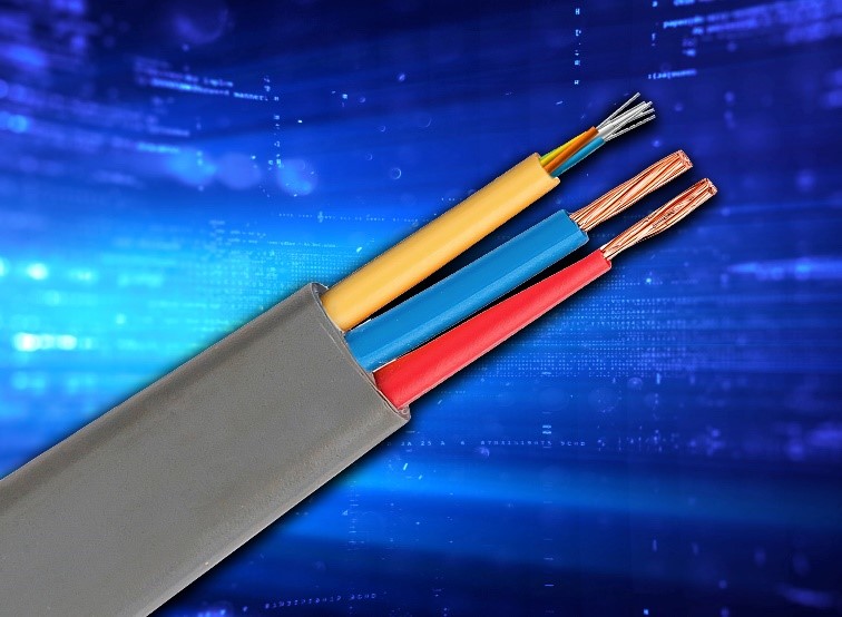
Hybrid Cable Construction
Hybrid copper-fiber cables are available in a variety of constructions, including multimode or singlemode fiber. They can include a single fiber or multiple fibers depending on the application and number of devices being connected. For example, optical network terminals (ONTs) used in passive optical networks operate over a single fiber whereby signals are transmitted simultaneously in both directions over separate wavelengths using wavelength division multiplexing (WDM) technology—1310nm for upstream data and 1490nm for downstream data.
The copper conductors for power within a hybrid cables also range in number and type depending on how many devices are being connected and the power requirements. For example, some hybrid cables may contain as many as 12 copper conductors to connect to remote power supply units or just two conductors to connect to a single device.
The copper conductors also typically range from 12 to 20 AWG, which directly impacts how much power they can deliver over certain lengths, with larger conductors capable of carrying more power over greater distances. For example, Corning’s composite fiber-copper cables with 12 AWG conductors can deliver up to 75W of power up to 457m (1.500 ft.), while 20 AWG conductors can only carry 75W of power up to about 71m (235 ft.). The size of the conductors is therefore a critical factor when selecting a hybrid copper-fiber cable.
Class 2 Power Delivery
It’s important to note that PoE is only supported by balanced twisted-pair copper cabling (e.g., Category 6, Category 6A, etc.) as it is an Ethernet-based protocol per IEEE 802,3 standards that delivers DC power using common mode voltage on two or four pairs. From an industry standards perspective, it is also only supported to 100m distances, but as mentioned in our Breaking the 100-Meter Barrier blog, some vendors have claimed it can be supported to greater lengths using extended-reach cable and other means.
Some may also not realize that while PoE is considered a safe, low-voltage Class 2 circuit per the NEC®, not all Class 2 circuits are PoE—there are plenty of other Class 2 power applications where power is delivered from a DC power source over two conductors (positive and negative) to devices, such as thermostats, door bells, non-PoE LED lights, cameras and more. The copper conductors in a hybrid copper-fiber cable can be used to deliver this non-PoE Class 2 power. Some hybrid-fiber cables can also distribute Class 3 DC power to active equipment, lighting grids, commercial sound systems and life safety and security systems that require more power than Class 2 can deliver.
Testing and Troubleshooting Considerations
If you’re familiar with PoE, you’re probably aware that certifying your twisted-pair category cable per industry standards is enough to tell you that you will be able to support PoE. You can also test PoE on an active network using a simple tester like Fluke Networks’ MicroScanner PoE that displays the power level at an outlet or switch port, along with the data transmission speed of the connection. It can also be used to test the PoE coming from devices that are powered via non-PoE Class 2 circuits, such as an ONT. The MicroScanner is also ideal for showing the distance to a break or short in the event that the cable is damaged.
But how does one test and troubleshoot hybrid copper-fiber cables delivering non-PoE Class 2 power? When it comes to installing hybrid copper-fiber cable, the fiber portion of the link is certified as any fiber cable would be via Tier 1 or Tier 2 testing (click HERE for more on that). For the power, it is recommended to carefully plan up front since deploying a Class 2 circuit needs to consider voltage drop (between source and device), distance, conductor size (AWG) and power requirements of the end device.
According to manufacturers like Corning, pre-planning is critical to ensure enough power to support a device based on its current draw and distance from the power source. Once the network is live, continuity, power and length can easily be measured using a digital multimeter in the event that a device doesn’t boot up. If there is no continuity due to physical damage, the location of that damage can then be pinpointed using a Fluke Networks’ Pro3000™ Tone and Probe. However, if pre-planning was flawed and the distance was too great or conductor size too small to support the power needs of the end device, there is little that can be done other than replacing the cable with a larger conductor size, shortening the distance of the circuit, or swapping out the end device for something that requires less power (none of which are ideal).
To avoid the potential for that costly scenario and ensure that the circuit will indeed meet the end device power requirements, it’s recommended to work with your hybrid cable manufacturer during the planning stage. There are also plenty of industry formulas and calculators that allow you to input power supply capability, remote power requirements, wire gauge and temperature to determine maximum cable length. And there really aren’t any risks if the circuit is capable of delivering more power than a device can handle since a device only pulls the amount of power it needs.


