Cable Testing 101: What’s My Loss Budget?
December 26, 2019 / General, 101 learning, Installation and testing, Upgrading and troubleshooting, Best Practices
While you might hear your CFO grumbling about staying under budget from a dollar perspective, staying under your loss budget from a fiber perspective has a much bigger impact on your network performance – which ultimately impacts your bottom line by avoiding downtime.
But how exactly is your loss budget defined and how do you ensure you don’t exceed it?

What is a Loss Budget?
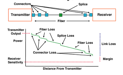
Expressed in decibels (dB), loss of signal happens along the length of any cable. It is a natural phenomenon that occurs for any type of transmission—electrical or data. And the longer the cable, the greater the loss. Loss also occurs at any connection points along the way such as connectors or splices.
Terminology can be confusing since most simply refer to “loss” when talking about loss budgets. The full name of the parameter is “insertion loss” – and to add to the confusion, insertion loss is also sometimes referred to as attenuation. In fact, standards used to call it “attenuation” but since that was more of a general term that refers to ANY reduction in the strength of a signal, the terminology changed to insertion loss.
Different fiber applications have different maximum insertion loss requirements to ensure that the loss isn't too high to prevent the signal from properly reaching the far end. Loss budgets should be determined during the early design stage to make sure your cable plant does not exceed the maximum specification for your application.
What Do I Calculate?
Your loss budget is made up of all the components in your channel, including fiber, connectors, splicing, splitters and couplers. The active equipment also needs to be considered per the equipment manufacturer’s specifications based on any differences between transmitters and receivers, as well as some margin to account for loss of power over time that can occur due to transmitter age.
Since insertion loss is directly related to length (which explains why there are standards-based distance limitations per application), the length of any cable in your channel needs to be included in the budget. For a shorter length of cable, the loss will be less. For example, the typical loss of OM4 laser-optimized multimode cable is about 3dB/km for transmission at the 850nm wavelength. This translates to 0.003dB per meter. So, if your cable length is 50 meters, your loss for the cable is roughly 0.15dB, while at 100 meters, your loss will be 0.3dB.
You also need to include the loss of any connections in your cabling plant. Manufacturers will provide a specification for their connectors. Note that this value is based on factory testing when mating connectors to a high-quality reference connector, so it’s important that your connectors are mated to similar quality connectors. While TIA standards specify a maximum insertion loss for connectors of 0.75dB, most manufacturers’ connectors have a typical insertion loss that ranges between 0.2 and 0.5dB.
All splices within your cable plan also need to be calculated as part of your loss budget. Multimode splices can be as low as 0.1dB, but TIA standards specify a maximum of 0.3dB. This is a good value to use when calculating loss budgets since the quality of the splice can vary based on the expertise of the technician.
How Do I Know I’m Within Budget?
First, you need to know what the maximum insertion loss is for the application you plan to run, as well as any future applications that might run over the same cabling plant. Higher bandwidth applications have more stringent loss requirements. For example, 10 Gb/s multimode (10GBASE-SR) applications have a maximum channel insertion loss of 2.9dB over 400 meters of OM4 multimode fiber, while 40 Gb/s multimode (40GBASE-SR4) applications have a maximum channel insertion loss of 1.5dB over just 150 meters of OM4. With these more stringent requirements, staying within your loss budget is more critical than ever.
Let’s look at an example. Considering 3.0dB/km fiber loss, an OM4 150-meter length of fiber will be equal to about 0.45dB. For a 10GBASE-SR application, that leaves 2.45dB (2.9dB – 0.45dB) for connectors, splices and other components. For a 40GBASE-SR4 application, that leaves just 1.05dB (1.5dB – 0.45dB). If then adding four 0.3dB connectors into the channel, your total budget for 10GBASE-SR would be 1.65dB (0.45dB + 1.2dB), which leaves plenty of headroom of 1.25dB. For a 40GBASE-SR4 application, however, the 1.65dB loss for the cable and connectors is over budget by 0.15dB. In this case, you would need to consider reducing the number of connectors in the channel or perhaps choose lower-loss 0.2dB connectors.
Further, loss budgets should always have a little wiggle room, so it’s better to be a bit conservative and leave yourself some margin—especially if you’re considering field termination or splicing, which have the potential for installation variables that cause loss such as air gaps or poor fiber core alignment. Extra margin to accommodate for reconfigurations, restorations or splice degradation within the cable plant should also be considered. It’s also important to remember that the connectors on both ends of the channel need to be included in the loss budget – when channel testing, your test reference cords will mate with those connectors to include their loss.
Each fiber application standard also specifies a distance limitation for various types of fiber. So, even if you are within the loss limits for an application, you also need to be within the length limits. You can read more about that here.
Regardless of what you come up with for your loss budget calculation, the only way to really know if you’ve stayed within budget is to test the insertion loss of the channel after installation via Tier 1 testing using an optical loss test set like Fluke Networks’ CertiFiber® Pro. And best practice to continually improve your loss budgeting is to always compare what you calculated during the design phase to your actual test results.


