How to Test Shield Integrity?
February 15, 2017 / General, 101 learning, Installation and testing, Upgrading and troubleshooting, Best Practices
Back when Wolfenstein 3D was all the rage, we set up an exhibit at a BICSI conference where we tried to make a Cat 5 link fail by inducing noise onto it. We tried all kinds of no-no’s, such as placing the cable next to a fluorescent ballast, a large electric motor, and even the coil of a running car’s engine, yet the link provided virtually error-free 100BASE-TX performance. At that point, it didn’t seem like there would be much benefit for screened cable for the vast majority of installations.
 While we moved on to Grand Theft Auto and Halo, and data rates and frequencies increased, a curious thing happened. Interference coming from outside sources remained a minor problem but the interference between the cables in a run became a significant issue. This led to the requirements for testing for Alien Crosstalk (AXT), which requires extra work on the installer’s part. Since shielded cabling greatly reduces AXT, the value of a shielded cable becomes apparent.
The AXT problem would become unmanageable with unshielded cabling at the frequencies required for Category 8 cabling, so all Category 8 cables are shielded. Research on the issue also found out that if the shield is not terminated properly at both ends, the AXT performance can degrade by 10 dB or more, which is enough for most installations to move from a PASS to a FAIL. So Category 8 cabling requires shielding that is properly terminated to the connector at both ends.
And that’s how the systems are designed. But as experienced installers know, just because something is designed a certain way, doesn’t mean that’s how it’s going to end up in the field. That’s why we have testers. Field testers can test the shield to make sure it is properly connected at both ends.
The easiest way to test shield integrity is with a DC continuity test. Put a voltage on the cable at the near end, and if it shows up at the far end, it is assumed to be connected properly. While that is true for the conductors in the cable, it’s not necessarily true for the shield. That’s because the shield is connected to the exterior of the connector, and the connector is in physical contact with the rack panel. The rack panel is connected to the rack, which is connected to the bus bar, which is connected to ground, which is connected to the far end bus bar, etc. until you reach the connector at the far end. So the DC test signal can start at the connector, travel through this convoluted alternate path, and show up at the other end. (There are other possible paths as well, such as through the screen of an adjacent cable.) The tester doesn’t know which path the signal followed, so it’s fooled into believing the shield is connected – whether or not the shield is connected and even if the cable has no shield at all!
For that reason, the Cat 8 testing standard states “for Level 2G testers it is understood that the screen continuity is tested along the path of the cabling” (TIA 1152A Clause 4.2.2). This means a 2G compatible tester has to be able to tell whether the shield is properly connected from the near to the far end and not be fooled by an alternate path as described above.
The Fluke Networks DSX CableAnalyzer Series has this capability. This makes the DSX-8000 and DSX-5000 fully compliant with this part of TIA 1152A (not to mention all the other parts – click here for an Intertek report on DSX Series compliance).
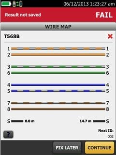
Not only does this feature verify that the shield is connected properly, but it can also help you troubleshoot it if it’s not, by telling you the distance to the shield connectivity failure (see image). This can save a lot of troubleshooting time.
(You can also see a great video of this feature in action with the DSX-5000 here. Note that the feature works the same way in the DSX-8000.)
Publicações recentes Ver tudo >
Mais publicações gerais Ver tudo >


©2006-2021 Fluke Corporation。保留所有权利。
RM2011, 20/F, SCITECH Tower, 22 Jianguomenwai Avenue, Chaoyang District, Beijing, China
地址:北京市朝阳区建国门外大街22号赛特大厦20层2011室
联系电话:400-8103435
沪ICP备11037028号-15![]()