Electromagnetic Interference Mitigation in Industrial Ethernet Cabling
9 de abril de 2020 / Geral, Padrão e Certificação, Redes Industriais
While standard and Industrial installations of Ethernet share many of the same characteristics, such as frame sizes, signal levels and data rates, there are significant differences as well. One of these is the physical environment in which the cabling system operates.
International standards TIA1005 and ISO 11801:3 detail what is commonly referred to as the M.I.C.E. requirements for Industrial Ethernet cabling systems. “M” indicates the mechanical environment – cables may be subject to severe mechanical forces, such as shock or being crushed or something as mundane as repeated flexing. “I” stands for “ingress”, addressing the fact that connectors need to be able to block the entrance of liquids, dust, and aerosols from areas where they can damage sensitive electronics. Chemical and Climactic concerns make up the “C”, referring to harsh temperature, humidity, and chemicals that can damage office-grade cabling.
This brings us to “E”, which refers to Electromagnetic Interference and Electrostatic Discharge. Devices such as motor drivers, welders, and induction heaters are the worst generators of electromagnetic noise that can affect the network performance. In an office environment the number of such noise sources is close to zero. Further, electrical power cables supplying these devices can generate magnetic fields that interfere with data transmission.
Let’s look at a typical situation. If you install an Ethernet cable (a metal conductor) passing through a magnetic field (for example close to a big motor), an electrical current is generated in the cable and as a result the Ethernet signal (which is also an electric current) will be distorted. What does it mean for the data transmission? The packets’ integrity is compromised, and it may cause intermittent communications. In an office, this usually means a re-transmission of the packet, which is likely not even noticed by the user. In an Industrial setting, where timing is critical as a result of mechanical processes, this could lead to squirting the ketchup on the floor, a failed weld or even a shutdown of the line.
Preventing noise problems is obviously important to Industrial Automation and there are a number of ways to approach the issue. Most installations can and do operate successfully with UTP cabling due to its cost, ease of installation and maintenance and the lack of issues that come with other methods. Newer UTP cables can also provide superior noise immunity. But let’s look at other approaches first.
Fiber Optic Cabling is completely impervious to electromagnetic interference and is by far the most complete solution to “E” problems. However, fiber cabling has some drawbacks. First, it is more expensive – not necessarily for the cabling itself, but the electronics for connecting to fiber are typically much more costly and for many industrial devices may not be available. Fiber-to-copper transceivers can solve that problem but add their own expense and another point of failure that also requires power. Another issue with fiber is that it requires specialized tools for installation and troubleshooting which can be costly. And fiber is very sensitive to contamination from dust or moisture on the end-faces, which can be a significant problem in industrial environments. Technicians also need expertise to work with fiber, although some newer equipment makes it easy to find faults, for example (Figure 1).
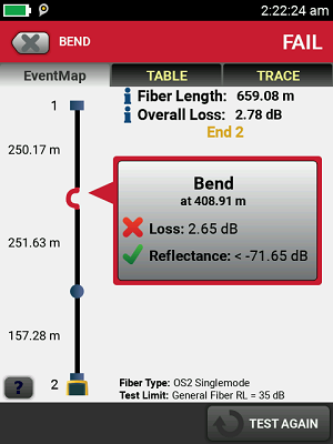
Figura 1. Advanced OTDR’s such as the OptiFiber™ Pro display problems in easy to understand graphics.
Avoiding Noise Sources can reduce their impact as well. Careful routing of cabling away from EMI sources such as variable frequency drives (VFD), high power cabling, and welders can reduce interference and packet loss. The problem is that you won’t really be sure how much it solves the problem. And new devices that cause EMI may be added or moved closer to the cable in the future leading to problems.
Shielded / Screened Cabling can nearly eliminate noise issues. The shield acts as a cage that prevents any electromagnetic noise from getting into the cables, absorbing and conducting this energy through a low impedance path to the ground. In exceptionally noisy environments, a combination of foil and braid shields work better for protecting the cable against EMI and to provide a low impedance grounding path. In moderately noisy areas, an overall foil shield may be sufficient. However, shielding presents challenges of its own. Due to differences in ground voltages across a factory, grounding must be approached carefully. A shielded cable needs to be grounded in order to work efficiently and protect the data transmission, but should one ground the cable at one end or at both ends? Each application has its own unique environmental noise and grounding situations require engineering practices and experience to make the decision.
Industrial Ethernet protocols (Ethernet/IP, Profinet, Modubus TCP) also provide recommendations for shield grounding to maximize immunity to ground offsets. These extensive/expensive grounding techniques prevent ground loops from causing problems. One recommendation is cutting of the outer jacket to expose the shield and then clamping the cable in a copper block that is connected to 8mm thick copper ground in multiple places on each cable run, a time consuming and costly approach. Testing the cable’s shield can be difficult as well. Our DSX CableAnalyzer™ provides a unique ability to measure the continuity of the ground along the path of the cable to ensure that grounding is done properly (Figure 2).
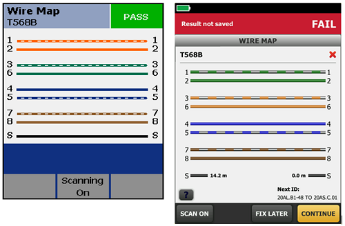
Figura 2. Older testers (left) use a simple resistance test to check for ground continuity, which can be “fooled” by alternative ground paths. The DSX CableAnalyzer (right) can pinpoint shield failures even in the presence of alternative ground paths.
Highly balanced UTP cables can be resistant to EMI and in addition can mitigate the issues with ground offsets and ground loops common in control applications and screened cables. Most manufacturers recommend UTP cables, and highly balanced ones provide an additional measure of protection. To test a cable for noise immunity, a balance measurement of Transverse Conversion Loss (TCL) and Equal Level Transverse Conversion Loss (ELTCTL) can be executed. Manufacturers of cabling will specify the performance of their cable in one of three levels: E1 for offices, E3 for high EMI environments and E2 in between. Our DSX CableAnalyzers can perform field testing of TCL and ELTCTL to verify noise immunity and whether a cable link provides adequate performance in noisy environments (Figure 3).
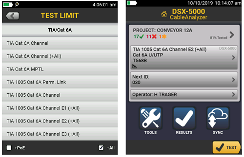
Figura 3. TIA limits for E1 through E3 can be selected in the DSX CableAnalyzer
If you want to know more information about how to mitigate Electromagnetic Interference in an industrial environment and how a field cable tester can help you in preventing intermittent communication, do not hesitate to reach out..


