AVISO: Cannot measure backscatter (OptiFiber)
If your test report from the OTDR has this warning message: Cannot measure backscatter......
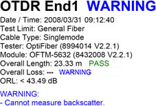
....it is indicating that the OTDR is unable to measure the Overall Loss of the link. There are two possible causes. Your fiber optic link is shorter than the attenuation deadzone of the OTDR, or you have a mated connection with poor reflectance. To better understand this, let's review what the attenuation deadzone is before you start adding a a receive fiber to your link.
Zona neutra de atenuação
This refers to the minimum distance required, after a reflective event, for the OTDR to measure a reflective or non-reflective event loss. To measure short links and to characterize or find faults in patch cords and leads, the shortest possible attenuation dead zone is best.
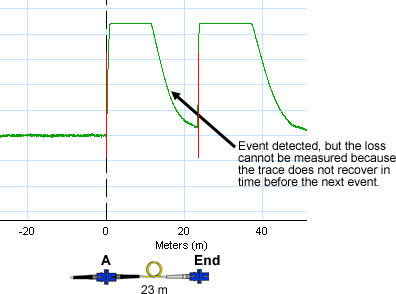
In the example below, the OTDR is said to have an attenuation deadzone of 12 m @ 1550 nm on singlemode fiber. Since the link is 23 m, greater than the attenuation deadzone, you would expect the OTDR to be able to measure the attenuation loss of the event "A" here and hence the Overall Loss of the link. But it can't, since the trace from event "A" does not recover in time before the end event.

Figure 1a
Let's take another example using the same OTDR. As above, the link is also 23 m, but since event "A" does recover in time before the end event, the OTDR is able to report the attenuation loss of event "A" AND the Overall Loss of the fiber link.
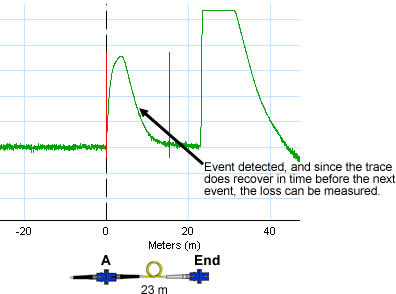
Figure 1b
The attenuation deadzone is affected by the pulse width and the reflectance of the event. When you look at the specification for an OTDR, you will see a table similar to that below:
Comprimento de onda
OptiFiber
DTX OTDR
850 nm
4,5 m
10 m
1300 nm
10,5 m
13 m
1310 nm
8 m
10 m
1550 nm
8 m
12 m
Tabela 1. Attenuation Deadzones
The OTDR vendor may or may not specify the pulse width they are using to determine the attenuation deadzone. The OTDR vendor will typically pick a narrow pulse width, since that will yield the best attenuation deadzone. As your link increases in length, so will your need to increase the pulse width. Increasing the pulse width causes the attenuation deadzone to increase. If you leave the OptiFIber or DTX Compact OTDR in AUTO mode, the testers will select the optimum pulse width for you automatically (recommended).
Often missing from the OTDR specification is the reflectance value the OTDR vendor is using when quoting the attenuation deadzone. In the case of Fluke Networks, the attenuation deadzone is specified as:
- Multimodo
Measured at ± 0,5 dB beyond backscatter for typical connector with UPC polish (reflectance of < -37 dB multimode) using 40 ns pulse
width (20 ns at 850 nm) at near end (100 m, which excludes dispersion).
- Monomodo
For singlemode: measured at ±0,5 dB beyond the backscatter for a typical singlemode UPC connector (< -50 dB reflection using 20 ns
pulse width).
Looking at the two examples again but side by side this time, it becomes clear that the better the reflectance, the more likely the OTDR is able to measure the attenuation loss of an event.
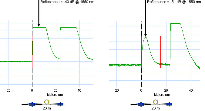
Figura 2
What happens to your attenuation deadzone when the reflectance is just -26 dB? An example is shown below:
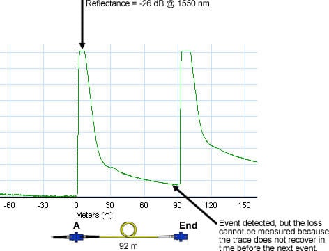
Figura 3
With a reflectance of just -26 dB, you see much more "tailing" from event "A". This results in an attenuation deadzone of more than 100 m, even with a short 20 ns pulse. The optical loss/length test using an Optical Loss Test Set (OLTS) also failed the link (when tested to ANSI/TIA-568-C.0).
But what you may see is that the Optical Loss Test Set passes the link, yet the OTDR gives a WARNING. If we look at Figure 1a again:
(Figure 1a)
and the corresponding optical loss/length report from the OLTS, we see a PASS:
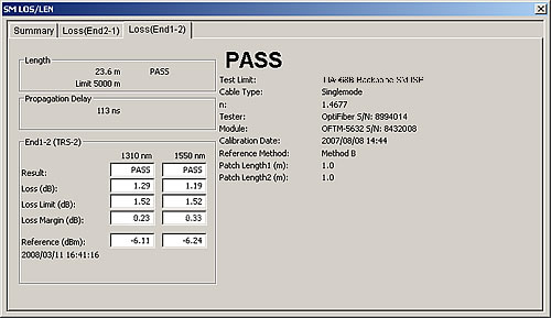
Table 2
The OTDR uses a different measurement technique compared to the OLTS. The OLTS does not rely on backscatter to make its measurement. Therefore, the reflectance can be quite bad and yet the OLTS shows a PASS, as in the example above.
Is the example above (Figure 1a) a failure? As far as the standards are concerned, NO. Reflectance is not currently a test requirement in the TIA, ISO/IEC and EN cabling standards. But, the OTDR is unable to make an accurate loss measurement due to less than desirable reflectance. That results in a dilemma for Fluke Networks. We cannot report a FAIL, because reflectance is not a requirement. We cannot report a PASS, because we are unable to calculate the Overall Loss of the link. The only suitable summary for the result is WARNING.
It's worth noting at this point that most OTDRs do not calculate the Overall Loss of the link automatically.
Field polishing?
If you are field polishing connectors, you are at an immediate disadvantage when it comes to OTDR testing. You've seen how poor reflectance can result in larger attenuation deadzones and WARNING appearing on the test report summary. If you are lucky to have a really good fiber technician on your staff, who is given adequate time to polish connectors, you can expect a reflectance value of -35 dB or better. But, even with a reflectance of -35 dB, your attenuation deadzone on singlemode fiber is going to be around 30 m. Therefore, if you have links less than 30 m, you will need to use a Receive Fiber for the OTDR to be able to measure the Overall Loss.
The problem with field polishing is that the technician only gets to see a two dimensional image of the endface connector. An example of a multimode connector endface is shown below:
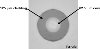
figura 4
This is a good example of how the endface of a connector should look. There are no scratches, chips, resin or oxides visible. BUT, what you cannot see is the endface geometry. Let's look at the fiber connector from the side view.
figura 5
The only way to tell if the fiber is protruding from the ferrule (not enough polishing), or if the endface has been too aggressively polished (undercut), is to use a device called an interferometer.
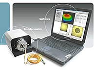
Figura 6. Example Interferometer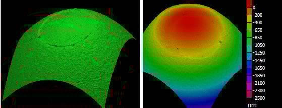
Figura 7. Example "< 50 nm undercut" image from an Interferometer
It is only with an Interferometer can you guarantee good endface geometry and reflectance.
The field polishing process
Most polishing sequences begin with aggressive materials, silicon carbide to remove epoxy and diamond lapping films for the beginning and intermediate polishing, that remove both the ferrule and fiber at the same rate. During the last polishing step a less aggressive material, usually silicon dioxide, is used because it attacks only the fiber. If an aggressive film is used for the final polishing step, excessive undercut will result.
Excessive Fiber Undercut is usually specified as more than 50 nm. Fiber Undercut is a condition that affects both reflectance and insertion Loss. When connectors are mated, the ferrule material surrounding the fiber compresses, which optimally allows fibers with an acceptable undercut/protrusion to make contact. Fibers that do not make intimate contact have an air-gap. An air-gap will produce unacceptable reflectance and insertion loss. Practically speaking, insertion loss is not the real victim here, reflectance is.
So we're asking the technician to polish within 50 nm? And we're not going to give him an interferometer?
If field polishing is starting to sound a little daunting, then let's introduce two alternatives.
Unicam®
These are connectors than have been pre-polished in a factory with automated machines. They are often UPC (Ultra Physical Contact) in nature and have very good reflectance. Depending on the vendor, you can expect better than -40 dB for multimode and -50 dB for singlemode connectors.
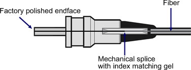
Figura 6
You will still need to clean and inspect the endface before making any measurements!
Pigtails
Out of the three options presented here, this is the most desirable. But, it requires a fusion splicer which is a considerable initial expenditure. However, you get it back in the labor cost saved. Similar to the Unicam connectors, the end faces are factory polished. A length of fiber is left dangling out the back of the connector; hence the term pigtail. This fiber is then fusion spliced onto the installed fiber. A modern fusion splicer will give a splice loss of <0,1 dB and reduces the uncertainty of having to reconnectorize due to a technician issue, which can happen with Unicam style connectors. You will still need to clean and inspect the endface before making any measurements!
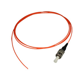
Figura 7
Unicam® is a registered trade mark of Corning Cable Systems Brands, Inc.


