DC contact resistance issues
Introdução
Ever certified a link yet the application was having issues? There could be many reasons, one of those being a DC Contact Resistance issue. But surely the certification process would reveal such an issue? Not quite. A standard TIA Category 5e, 6, 6A or ISO/IEC Class D, E, EA field test can miss DC Contact Resistance issues.
What can you do about it?
Ask for DC Resistance Unbalance within a pair. Whilst it is a requirement of the cabling system standard ANSI/TIA-568-C.2, it is not a mandated field test in ANSI/TIA-1152, titled Requirements for Field Test Instruments and Measurements for Balanced Twisted-Pair Cabling. The table below shows how certain field tests are excluded in ANSI/TIA-1152:
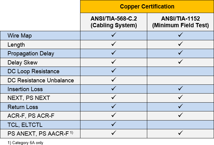
That lack of a requirement for field testers to measure DC Resistance Unbalance within a pair can result in DC Contact Resistance issues going undetected. Balance measurements (TCL and ELTCTL) are also absent from the field test standards. For those operating to ISO/IEC 11801, the story is similar:
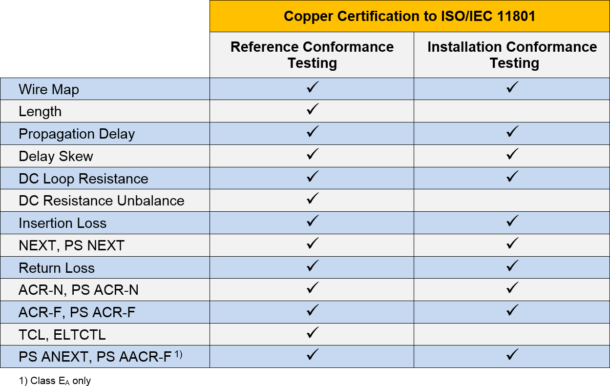
In ISO/IEC 11801, reference conformance testing is testing in a laboratory, installation conformance testing is field testing. Additionally, length is an informational test only in ISO/IEC 11801. It is not required for conformance to the standard.
DC Resistance Unbalance (within a pair)
Defined as the unequal resistance in the two wires of a transmission line. Let's looks at an example measurement:
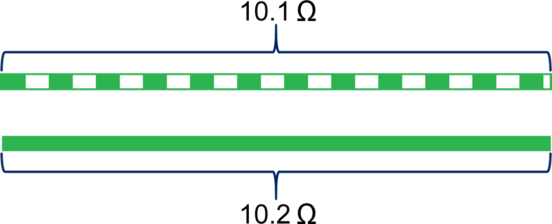
- DC Loop Resistance = 10,1 Ω + 10,2 Ω = 20,3 Ω
- DC Resistance Unbalance within a pair = |10,1 Ω - 10,2 Ω| = 0,1 Ω
This is not a new requirement. It can be found in ANSI/TIA/EIA-568-B.2, published back in 23 de abril de 2001. It was carried across into ANSI/TIA-568-C.2, published 11 de agosto de 2009. It has gathered more attention in recent years with the prevalence of Power over Ethernet (PoE) devices, where this parameter is key for successful operation. You will also find it in the IEEE 802,3 Ethernet standards.
A standard Category 5e field test (ANSI/TIA-1152)
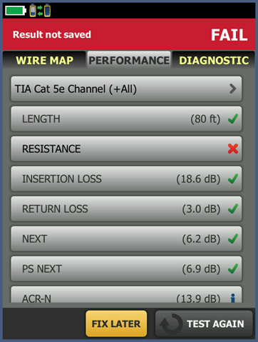
Below is a screen shot from a DSX-5000 CableAnalyzer. This is a standard ANSI/TIA-1152 Category 5e field test, one of the most common field tests conducted today. The customer was reporting issues with their links. Because the patch cords were a concern, the entire link was tested with the patch cords in place, hence the use of the Channel limit. If this were an installed link with no cords, you would select a Permanent Link test.
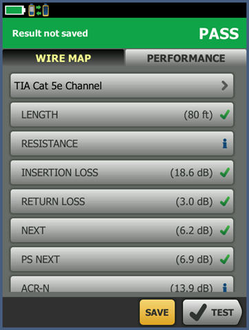
From the summary results screen above, this link appears to be good. Why would you question it? But if we tap RESISTANCE on the screen above:
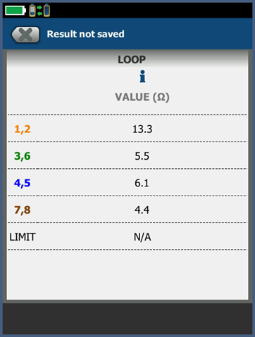
Pair 1,2 has a significantly higher DC Loop Resistance (13,3 Ohms) when compared to the other pairs. You can expect each pair to be slightly different due to the different twist rates in the pairs, but not by this amount. Something is not quite right here. Experience tells us that there is a DC Contact Resistance issue somewhere in the link. But if you did not drill into the Resistance reading, you would never know - until the application had issues of course. But wouldn't Insertion Loss fail if there was a DC Contact Resistance issue? Data from the field suggests that is not always the case, as in this example here.
The lack of a PASS/FAIL for DC Loop Resistance (shown above) is a direct result of ANSI/TIA-1152 not requiring DC Loop Resistance for compliance. On a positive note, ANSI/TIA-1152-A when published will require DC Loop Resistance for compliance. However, even if the 25 Ohm limit found in ANSI/TIA-568-C.2 or ISO/IEC 11801 was applied to this link, it would still pass, even though it has a DC Contact Resistance issue.
An enhanced Category 5e field test (ANSI/TIA-568-C.2)
Testing this link again to include DC Resistance Unbalance within a pair resulted in a FAIL. To the technician and end user, it's clear that something is wrong with this link.
If we tap RESISTANCE on the screen, two additional Resistance tests are now reported:
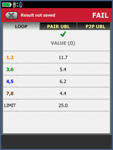
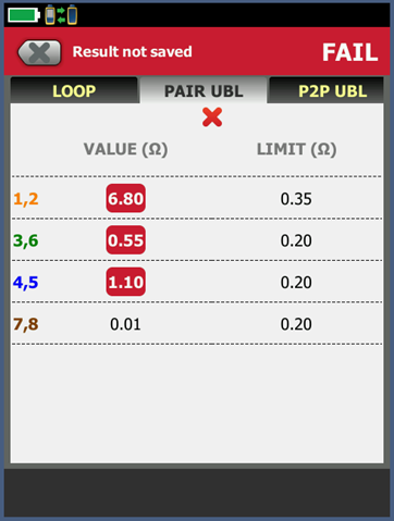
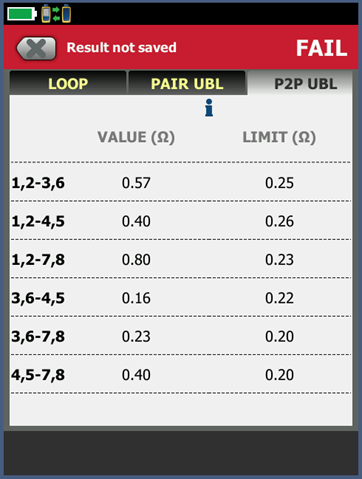
In order to support next generation PoE devices, the IEEE and TIA have specified a new test parameter, DC Resistance Unbalance between pairs. The numbers are subject to change as they work on the standard, so no PASS/FAIL is given at this time, although draft limits are provided for guidance. For the observant reader, you may have noticed a change from 13,3 Ohms to 11,7 Ohms for DC Loop Resistance between the two tests. When you have a DC Contact Resistance issue, the reported resistance will fluctuate - such is the nature of these issues.
What caused this?
In this example, poorly made patch cords. Other causes can include broken wires at the IDC block or contamination of the lead frames inside the jack. The use of copper cladded aluminum cable can also throw up resistance issues.
Conclusão
DC Resistance Unbalance within a pair can detect a DC Contact Resistance issue that could otherwise undetected with a standard field certification test. But you have to specify a DC Resistance Unbalance test, it is not a field test requirement for either ANSI/TIA or ISO/IEC standards. This measurement is available in the DSX-5000 CableAnalyzer and will add approximately one second to the autotest time. Since the DSX-5000 CableAnalyzer can also make TCL and ELTCTL measurements, you may wish to specify these for your field tests too. They will add between three and five seconds to the autotest. Selecting a test limit with a suffix of (+All) in the test limit name will ensure Resistance Unbalance within a pair, Resistance Unbalance between pairs, TCL and ELTCTL measurements are carried out. You may wish to specifically call out the test limit name in your test specification.
The following (+All) limits can be found in Version 6.0 (and later versions) for the DSX CableAnalyzer Series:
- TIA Category 6A Perm. Link (+ todos)
- TIA Category 6 Perm. Link (+ todos)
- TIA Category 5e Perm. Link (+ todos)
- TIA Category 6A Channel (+All)
- TIA Category 6 Channel (+All)
- TIA Category 5e Channel (+All)
- TIA 1105A Category 6A Channel (+All)
- TIA 1105 A Category 6 Channel (+All)
- TIA 1105A Category 5e Channel (+All)
- ISO11801 PL2 Classe Ea (+ todos)
- ISO11801 PL3 Class Ea (+All)
- ISO11801 PL Classe E (+ todos)
- ISO11801 PL Classe D (+ todos)
- ISO11801 Channel Class Ea (+All)
- ISO11801 Channel Class E (+All)
- ISO11801 Channel Class D (+All)
Here is an example of a LinkWare PC test result for an Autotest containing (+All) measurements.


