Using a Category 5(e) Channel Adapter to test Category 6 DSP4x00 CableAnalyzer
Obs.: This article references the DSP cable analyzers which have been discontinued. See the upgraded, replacement DSX cable analyzers.
- LinkWare Version 6,2
With an ever-increasing number of manufacturers promoting the Channel Warranty, many installers are finding themselves required to provide Channel test results. This paper looks at the challenges of testing Channel links for both the installer and end-user. Lets start with the basics and understand what the Channel is.
The Channel test configuration is only to be used by system designers and users of cabling systems to verify the performance of the overall Channel or system. The Channel can include up to 90 meters of horizontal cable, a work area equipment cord, a telecommunications outlet/connector, an optional transition connection close to the work area, and 2 cross-connect connections in the telecommunications room. The total length of equipment cords, patch cords, and jumpers shall not exceed 10 meters. Most importantly, the connections to the equipment at each end of the Channel are not included in the Channel definition:
Figura 1. Channel Configuration
When you make the Channel measurement, it is only valid for the patch cords used at that moment. In other words, as soon as you replace any patch cords, the recorded measurement is no longer valid. This is because no two patch cords have the same performance. For this reason, it is impossible for installers to provide Channel test results for all links. However, it is becoming common for end-users to request Channel testing for a number of installed links with different lengths of patch cords. This then gives the end-user a greater degree of confidence that the entire system meets his/her expectations and not just the installed link. System manufacturers who promote Channel Solutions also increase the desire to test the Channel.
The challenge in making this measurement accurate lies with the field tester and available technology. If you refer to Figure 1, you can see that there are six connections that are sources of crosstalk (both NEXT and FEXT). What is key, is that the crosstalk generated in the connections to the field tester must not be included in the Channel measurement. At the local end of measurement, NEXT and FEXT properties have a different impact on measurement accuracy. The NEXT of the mated connection can be effectively removed using DSP techniques, we do this today in the DSP-4000 Series CableAnalyzers. This leaves us with FEXT to remove which cannot be done using DSP techniques. The Fluke DSP-4X00 channel adapter is designed to have far better FEXT performance (50 dB @ 100 MHz) than required for category 6 connectors (43,1 dB @ 100 MHz) to minimize its impact. At the remote end of measurement, NEXT and FEXT properties have a similar impact on the accuracy of the channel measurement, especially on shorter links.
Compensation of NEXT at the remote connector is only implemented in the DSP-4000 Series CableAnalyzers. Without this remote connector compensation, serious NEXT measurement errors at low frequencies are caused, particularly when the channel is short. The standards assume that there is no impact from the crosstalk in the remote adapter, which is only true for long links and higher frequencies.
A solução: RC2
The solution is simple remove the portion of NEXT generated in the remote connection. It sounds simple but it is extremely complicated because different lengths of Channels will give different amounts of reflected crosstalk. Fluke Networks devised a mathematical algorithm for doing this. To illustrate this, the amount of NEXT generated in the remote connection can be seen with a simple experiment. We took a DSP-4000 with Firmware Version 3,7 and made a Channel test on a 66-ft (20-meter) link. We then repeated the measurement with the same DSP-4000 but with Firmware Version 3,906 where the Remote Connector Compensation (RC2) has been implemented.
 |
 |
|
|
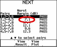
DSP-4000 |
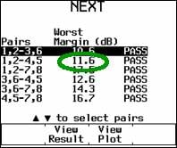
DSP-4000 |
figura 2 . Channel NEXT Remote Connector Compensation (RC2) Impact
By not implementing RC2, you are not showing the real performance of the installation. As you can see, we go from a margin of 7,1 dB to 11,6 dB with this particular system. Return loss is not such an issue, as in most cases the 3dB Rule will negate any bad Return Loss readings on short links. The impact of not having RC2 is shown in the NEXT graph below, taken from the same Autotest above.
figura 3 . Channel NEXT with and without Remote Connector Compensation (RC2)
The best channel measurement accuracy is obtained using effective NEXT compensation at the local and remote adapters, and selecting a channel adapter with excellent FEXT properties thats the DSP-4000 Series.
Produtos relacionados
Certificadores de cabos de cobre DSX CableAnalyzer™ Series


