Coaxial Cable Splitters – CableIQ
The following article discusses Coaxial cable splitters and addresses common questions on how the CableIQ can be used to evaluate the cabling system with coax splitters.
Quick questions:
- Will CableIQ detect coax splitters? Sim
- Will CableIQ locate coaxial cable splitters? May be, please read the article below in full.
- Will the CableIQ Identifiers work through a coax splitter? Click here
- Can I tell how many times the signal is split? Click here
What are Coax Splitters?
Coax splitters are used in video transmissions systems to take a single video feed and branch it off to multiple places. Coaxial cable splitters typically come in 2, 3, 4 and 6 way configurations. Ideally, a coaxial cable splitter maintains the proper impedance environment on both the input and output ports. For video coax systems, this impedance is typically 75 ohms. As the name implies, a coax signal splitter takes the power on the input port and splits it equally among the output ports. For example, a 2-way splitter has one input port and two output ports. It sends half the power of the input signal to one of the output ports. The other half is sent to the other output port.
Is there a difference in the quality of coax splitters?
Not all coax cable splitters are created equally. Low quality coax splitters can adversely affect the video signal, causing excessive attenuation of the signal (signal loss) and multiple reflections which can cause ghosting (shadows on the picture). Figure 1 shows the difference in the construction between typical low and high quality 2 way splitters. The low quality splitter has a single ferrite which attempts to control the impedance of the splitter. This typically fails to produce a good wideband impedance match and results in unwanted reflections and signal loss. The high quality splitter has a printed circuit with multiple components that assure the performance of the splitter over a wide frequency (preferred).

Figura 1: Picture Comparing Low and High Quality Splitter Construction
Why do I care if there are splitters in the coax system?
It is often very useful to know whether there are splitters in a coax distribution system and to be able to assess the splitter quality. Its also useful to determine how many times the signal is split on a specific run. Some installation practices only allow at most a 2 way split, so determining if there are multiple splitters is very important.
Can the CableIQ detect the presence of splitters?
Yes, the CableIQ can detect the presences of splitters in a coax system, but not always show their location (output branches must be un-terminated). In the past, detecting the presence of splitters, their quality and the number of splits has been very difficult to do without specialized test equipment. However, the technology implemented in the CableIQ now allows this information to easily be determined. The CableIQ running in Coax Discover Mode can detect the presence of a splitter in a coax run and alert the user. Once a splitter has been detected, the user can inspect the COAX TDR Trace to look at the reflections on the coax run and determine other information. The TDR trace will contain information to generally assess the quality of the splitter and how many times it is split.
The CableIQ implements a TDR (Time Domain Reflectometry) like technology that allows it to determine the location of impedance changes. TDR is like radar and signals reflect off each point where there is an impedance change. If the impedance change goes higher, for example an open circuit, the reflection is positive. If the change in impedance is lower then the reflection is negative. The size of the reflection is a function of the size of the impedance change. With this simple knowledge, a user can view the TDR trace and determine if there are impedance mismatches due to a splitter and how many times a signal is split.
Consider the following example of coax cabling which has a 2 way splitter being tested by a CableIQ (Figure 2). It has three branches of lengths L1, L2 and L3 respectively. L2 and L3 are connected to the output ports of the splitter and are un-terminated.

Figura 2: Example coax cabling test configuration with a splitter
When testing in Coax Discover Mode, the CableIQ can detect the presence of the splitter. Figure 3 shows the display with the Splitter or Fault warning that will be present if the CableIQ suspects a splitter is in the cabling under test. This is the cue to the user that the Coax TDR trace should be viewed for further information. The COAX Trace is accessed by pressing the F1 key.
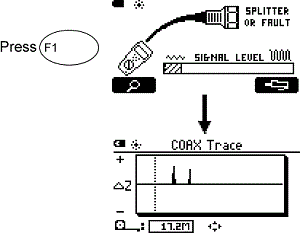
Figura 3: CableIQ Splitter Warning and Coax Trace Screens
What will the COAX Trace show if splitter is a high quality type?
An ideal or high quality splitter has the characteristic of looking like a 75 ohm impedance device across a wide frequency range on input and output ports. Therefore, when hooked into a 75 ohm cable system there will be little to no reflection at the splitter since there isnt an impedance change. Only the reflections off the un-terminated ends of the output branches will be seen. There should be one and only one reflection for each branch. The reflections should occur at the sum of the length of the input and respective output branches. Figure 4 shows a representative COAX Trace for this condition.
Interpreting the information in the COAX Trace allows important conclusions to be drawn. There are only two reflections. This is and indication the splitter is of good quality since there is no reflection for the splitter itself. The two reflections indicate that there is only a 2 way split. Note in the case of a good splitter the CableIQ may not be able to locate it since there is no reflection off a good splitters, but it can detect there is a splitter in the cabling. However, sometimes even in the case of a good splitter there may be a slight reflection that allows the user to determine the location of the splitter.
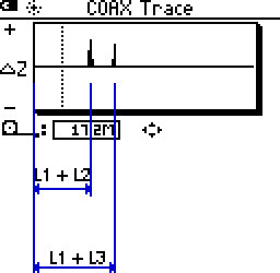

Figura 4: COAX Trace of high quality 2 way splitter
What if the splitter is a low quality type?
Low quality splitters do not provide a good wideband impedance match on all its ports and generally generate a low impedance reflection at the point of the splitter. This will produce a negative reflection. Since the impedance match is not good, unexpected extra reflections may be seen on the COAX Trace. Figure 5 shows the COAX Trace for the example test setup when a low quality splitter is used.
This COAX Trace shows there is a large negative impedance change at the point of the splitter. This indicates the splitter is not a good impedance match. There are three reflections after the splitter, not two as in the case of the good splitter. The first two reflections represent the ends of respective branches. The last one is due to some multi-reflection in the system caused by the poor impedance match of the output ports. his splitter should be replaced. Since it produces a large reflection, it is easily located at about 17,2 m from the CableIQ.
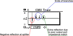
Figura 5: COAX Trace with low quality 2 way splitter has more than 2 reflections
Can I tell how many times the signal is split?
If there is a good quality splitter in the circuit, there should be one and only one positive reflection corresponding to each un-terminated branch on the coax circuit. This is easily verified by viewing the COAX Trace. Figure 6 shows an example where a 4 way splitter is seen in the circuit. There are 4 positive reflections in the COAX Trace.
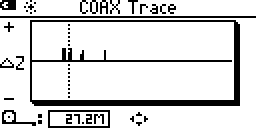
Figura 6: COAX Trace looking into 4 way splitter with un-terminated branches has 4 positive reflections.
Will the CableIQ Wire Map or Office ID Adapters work when there are splitters?
The ability for the adapters to work depends on the construction of the splitter. Most low quality splitters have a direct wire path from the input to output and the adapters will generally function with these splitters in the circuit. However, higher quality splitters (circuits) generally do not have a direct connection from the input to output. The connection in these devices is generally through some form of transformer device which does not pass the signaling the CableIQ and adapter required to function. MultiMap capability is not supported in Coax mode, so even if there are low quality splitters which have a direct connection, multiple adapters will not been seen.
Make sure unused ports are terminated
For example, if you have a 4 port splitter and are only using two of the output ports, the remaining two ports SHOULD be terminated. If not, expect to see a trace similar to that below:
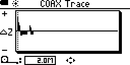
Figura 7: COAX Trace looking into 4 way splitter with unused ports left un-terminated

