ISO/IEC 14763-3 testing LC to LC (Duplex Multimode) DTX-EFM2
This article is for the Encircled Flux compliant DTX-EFM2 modules, testing LC to LC duplex fibre links to ISO/IEC 14763-3 (ISO/IEC 11801 Edition 2,2 2011-06).
The Encircled Flux requirement can be found in IEC 61280-4-1 edition 2.
You can learn more about Encircled Flux (EF) at http://www.brighttalk.com/webcast/727/62347, hosted by FOTC, TIA's Fiber Optic Consortium.
Any deviation from the test method below cannot be tolerated if you wish to remain Encircled Flux compliant.
Items required in addition to a DTX CableAnalyzer:
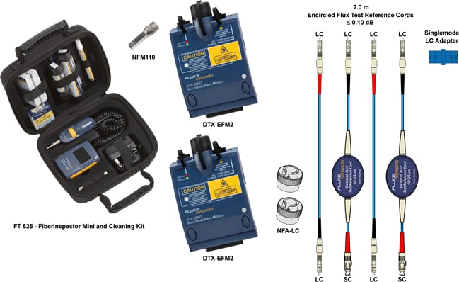
Inspection is critical. You can use anything from a simple Fiber Viewer to a Video Scope such as the FiberInspector Mini shown above.
If you have no inspection equipment, you cannot proceed.
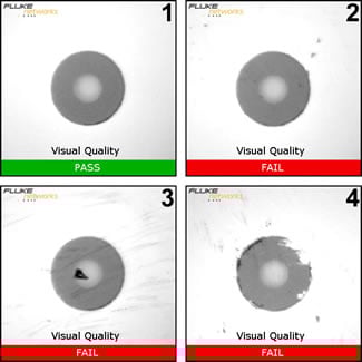
Let's define what is acceptable and not acceptable.
 |
|
The Test Reference Cords (TRCs) are critical to a successful measurement. To maintain Encircled Flux compliance, you MUST use one of the following two kits:
- MRC-50EFC-SCLCKIT: Duplex MM 50 µm TRC kit for LC links (Two SC to LC EF-TRC cords and two LC to LC TRC cords)
- MRC-625EFC-SCLCKIT: Duplex MM 62,5 µm TRC kit for LC links (Two SC to LC EF-TRC cords and two LC to LC TRC cords)
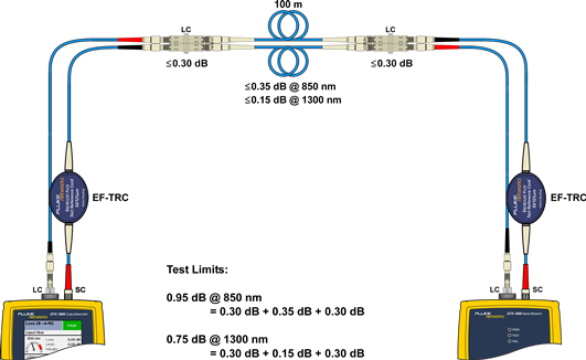
In this example, we're going to test a 100 m duplex 50/125 µm multimode fibre link with LC connectors at each end to ISO/IEC 14763-3 (ISO/IEC 11801:2010) whilst maintaining Encircled Flux compliance to IEC 61280-4-1 edition 2.
Setting up the DTX CableAnalyzer
-
With the DTX-EFM2 fibre modules inserted into the DTX CableAnalyzer, power up the main and remote units.
Sources will need at least five minutes to stabilize, longer in colder or hotter environments.
-
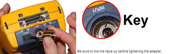
Replace the SC Adapters on the main and remote units with the optional LC Adapters.
-
Rotate the dial on the DTX CableAnalyzer to SETUP.
-
Select Fiber Loss and press ENTER.
-
Change the Test Limit to ISO/IEC 14763-3.
-
Change the Fiber Type to the cable you are testing.
This setting changes the Refractive Index (n) value. The DTX uses n to calculate the length of the fibre. You can manually enter the n values in Tab 3 of the Setup. If you cannot find your cable in the DTX Cable Library, look to the cable vendor's website for their datasheet. Since the ISO/IEC 14763-3 limit is calculated based on length, it is important to get this value right.
-
The Number of Adapters is going to be 2.
This is always the number of adapters per fibre strand added after the reference has been set.
-
Set the Connector Type to LC.
This will not affect the outcome of the result. It only affects the help screens.
-
Set the Test Method to 1 Jumper.

-
Inspect the TRCs. If needed, clean them and inspect again. You will not know if they are clean or not until you have visually inspected them.
-
Connect the Output port on the main unit to the Input port on the remote unit as shown below.
EF-TRCs must be used. Failure to do so will result in non Encircled Flux compliance.
-
Connect the Output port on the remote unit to the Input port on the main unit as shown below.
EF-TRCs must be used. Failure to do so will result in non Encircled Flux compliance.
-
Rotate the dial to SPECIAL FUNCTIONS.
-
With Set Reference selected, press ENTER then TEST.
-
You will then be presented with the results of the Reference.
For 50/125 µm it should be better than -24,50 dBm where -23,50 dBm is better than -24,50 dBm.
For 62,5/125 µm it should be better than -20,00 dBm where -19,50 dBm is better than -20,00 dBm.
These values reflect the cleanliness of the Ports and TRCs. The fact that your reference values are better than the minimum stated above does not mean they are good/clean. In the next few steps, we'll see how good/clean your TRCs really are.
-
Press F2 OK.
-
You can enter the length of your TRCs here. It does not affect the outcome of the test, but will be displayed on the test report.
-
Press F2 OK when done.
-
Rotate the dial to AUTOTEST and press TEST.
-
We're looking to make sure the sources have stabilized, so with Loss (Remote
 Main) highlighted, press ENTER.
If you see the loss deviate from 0,00 dB by more than 0,02 dB, your sources have not stabilized. This is an important step to avoid negative loss readings.
-
Press EXIT and then highlight Loss (Main Remote) followed by ENTER.
Again, if you see the loss deviate from 0,00 dB by more than 0,02 dB, your sources have not stabilized. This is an important step to avoid negative loss readings.
-
Remove the LC connectors from the Input Ports. Never disconnect from the Output Ports. Doing so invalidates the reference you just set.
-
Insert one of the LC to LC TRC's into the Input Port on the main unit.
-
Insert the other LC to LC TRC into the Input Port on the remote unit.
-
You are now ready to test the fibre link, but before you do, let's check out your TRCs. To do this, connect the main and remote units using a singlemode rated LC to LC adapter as shown below.
Obs.: The use of a singlemode adapter here is deliberate, to assure the best possible alignment of connectors. ISO/IEC 14763-3 requires the use of reference grade connectors.
-
Rotate the dial to AUTOTEST and press TEST.
-
To view the result, press ENTER and IGNORE the test limit. We're looking to make sure the loss is no greater than 0,15 dB @ 850/1300 nm.
This is the fibre connected to the Input Port of the main unit and it looks good.
-
Press EXIT and with Loss (Main
 Remote) highlighted, press ENTER.
This is the fibre connected to the Output Port of the main unit. ≤ 0,15 dB so we're good to go.
-
SAVE the test result so you have evidence of a good Set Reference and submit it as part of your documentation. This will avoid potential disputes later on. The Fluke Networks Technical Assistance Center will be asking for this data if support is required.
-
Disconnect the main and remote units.
Place dust caps on the remote TRCs if it is more than a short walk to the other end. According to the EPA, dust in an office can be anything from 2,5 µm to 10 µm so protecting the end faces is critical.
-
Connect the TRCs to the link you're testing
-
Press TEST.
The 0,30 dB at the connectors is not an error. This is the maximum permitted loss between a Test Reference Cord and a random fibre connector in ISO/IEC 14763-3. Let's take a look at another link with a fibre connector in the middle of it.
You will note the adapter count has increased to three and that the middle connection is permitted to be 0,75 dB. That's because the mated connectors in the middle do not involve a Test Reference Cord. These are two random mated connectors.
Test Reference Cord + Random Connector ≤ 0,30 dB
Random Connector + Random Connector ≤ 0,75 dB dB
The DTX CableAnalyzer will calculate the test limit (optical loss budget) for you.
Changing the number of adapters/splices will of course increase the test limit. Be sure the Number of Adapters is set correctly.
How often should I Set Reference?
The quick answer is; every time you begin to test a series of fibre links. It is critical to continually inspect the TRCs.


