Fiber Channel testing duplex LC to LC multimode fiber links using the DTX-MFM2 fiber adapters
This article describes the steps required to successfully certify a duplex fiber channel with LC equipment cords at each end.
Never use bend insensitive multimode fiber for test reference cords. Your 850 nm reading will be pessimistic.
ANSI/TIA-568-C requires the user to follow Method C (also known as 3 Jumper) for channel measurements. To measure the entire channel including equipment cords, a 3 Jumper reference is necessary. If not done correctly, the results can be very unpredictable.
IMPORTANT: A 1 Jumper reference is required first to ensure the TRCs are good before moving onto the final 3 Jumper reference.
Items required in addition to a DTX CableAnalyzer:
A limpeza é fundamental. It is the single most reason for ending up with negative loss values. You cannot clean without some means of visually inspecting the end face. This can be anything from a simple Fiber Viewer to a Video Scope such as the FiberInspector Mini shown above.
The Test Reference Cords (TRCs) are critical to a successful measurement. Your multimode TRCs loss should not exceed 0,10 dB at each end. The multimode TRCs shipped from Fluke Networks
NFK1-DPLX-LC Duplex MM 62,5 µm TRC for LC Adapter, Set of 2 (Suitable for testing OM1 fiber)
NFK2-DPLX-LC Duplex MM 50 µm TRC for LC Adapter, Set of 2 (Suitable for testing OM2, OM3 and OM4 fiber)
have a mated loss better than 0,10 dB at each hardened end face. And yes, you must inspect and clean these TRCs every time you use them - even new ones out of the bag. We'll show you how to check your TRCs for 0,10 dB loss later on in this article.
Where did Fluke Networks get that 0,10 dB requirement?
ANSI/TIA-568-C does not specify a maximum loss requirement for TRCs. However, ISO/IEC 14763-3 does and that's where the 0,10 dB for multimode and 0,20 dB for singlemode comes from.
In this example, we're going to test a 100 m (328 ft) duplex 50/125 µm multimode fiber link with duplex LC equipment cords at each end to ANSI/TIA-568-C.
Setting up the DTX CableAnalyzer
-
With the fiber modules inserted into the DTX CableAnalyzer, power up the main and remote units.
Sources will need at least five minutes to stabilize, longer in colder or hotter environments.
-
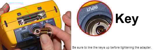
Replace the SC Adapters on the main and remote units with the optional LC Adapters.
-
Rotate the dial on the DTX CableAnalyzer to SETUP.
-
Select Fiber Loss and press ENTER.
-
Change the Test Limit to TIA-568-C Multimode.
-
Change the Fiber Type to the cable you are testing.
This setting changes the Refractive Index (n) value. The DTX uses n to calculate the length of the fiber. You can manually enter the n values in Tab 3 of the Setup. If you cannot find your cable in the DTX Cable Library, look to the cable vendor's website for their datasheet. Since the TIA-568-C Multimode limit is calculated based on length, it is important to get this value right.
-
The Number of Adapters is going to be 2.
This is always the number of adapters per fiber strand added after the reference has been set.
-
Set the Connector Type to LC.
This will not affect the outcome of the result. It only affects the help screens.
-
Set the Test Method to 3 Jumper.
-
Clean AND inspect the TRCs.
-
Connect the main and remote units together as shown below. This is not an error and is required to make sure the TRCs are good.
Ignore the help screen showing a 3 Jumper reference.
Mandrels must be used. Failure to do so can result in good fiber links failing. Red and grey mandrels are shipped with the fiber modules from Fluke Networks. The red is for 50/125 µm and the grey is for 62,5/125 µm TRCs.
-
Rotate the dial to SPECIAL FUNCTIONS.
-
With Set Reference selected, press ENTER (ignore the help screen) then TEST.
-
You will then be presented with the results of the Reference.
For 50/125 µm it should be better than -24,50 dBm where -23,50 dBm is better than -24,50 dBm.
These values reflect the cleanliness of the Ports and TRCs. The fact that your reference values are better than the minimum stated above does not mean they are good/clean. In the next few steps, we'll see how good/clean your TRCs really are.
-
Press F2 OK.
-
IGNORE the following screen and press F2 OK.
-
Remove the LC connectors from the Input Ports and put the dust caps back on them.
Never disconnect from the Output Ports. Doing so invalidates the reference you just set.
-
Insert one of the LC to LC TRC's into the Input Port on the main unit.
-
Insert the other LC to LC TRC into the Input Port on the remote unit.
-
Let's check out your TRCs. To do this, connect the main and remote units using a singlemode rated LC to LC adapter as shown below.
The use of a singlemode adapter here is deliberate, to assure the best possible alignment of connectors.
-
Rotate the dial to AUTOTEST and press TEST.
-
To view the result, press ENTER. IGNORE the test limit. We're looking to make sure the loss is no greater than 0,15 dB at 850 nm and 1300 nm. (The extra 0,05 dB is to take into account the uncertainty of the adapter used above for the TRC verification)
This is the fiber connected to the Input Port of the main unit and it looks good.
-
Press EXIT and with Loss (Main
 Remote) highlighted, press ENTER.
This is the fiber connected to the Output Port of the main unit. And again it looks good.
If it was more than 0,15 dB then you would want to inspect, clean and redo the Set Reference again. The higher this value, the more likely you are to see negative loss readings.
Can't get anywhere near 0,15 dB? They look ok under the FiberInspector? Your patch cords may not be ISO/IEC 14763-3 TRC rated. Please check with the supplier. Most cords come with the test results in the bag.
Tips:
If you are using the DTX where the temperature is not typical, run the TEST repeatedly with 1 minute intervals to see if the result changes. If it does, you will need to let the sources stabilize and repeat the Set Reference process again.
This procedure is likely to be new to the technician. Have them try this in the office before leaving for the installation.
-
Press SAVE to store the result as proof that the TRCs were good, use names such as "TRC1" and "TRC2".
-
Rotate the dial to SPECIAL FUNCTIONS.
-
With Set Reference highlighted, press ENTER and then TEST.
Now we are ready to add the third jumper to set a three jumper reference, but as before, we need to make sure the TRCs are good.
-
Disconnect the main and remote units.
-
Add a singlemode rated LC Adapter to the main unit.
-
Press F2 to continue.
-
Rotate the dial to AUTOTEST.
-
Add in your third test reference cord and press TEST.
Just as we did in Step 20, we now want to look to see what the loss is for both fibers.
We're looking for a loss no greater than 0,15 dB. The higher the reading, the more likely you are to see a negative loss reading.
-
Press SAVE to store the result using names such as "TRC3" and "TRC4" as evidence of good TRCs.
-
Rotate the dial to SPECIAL FUNCTIONS.
-
With Set Reference highlighted, press ENTER and TEST.
-
Remove the middle cord.
-
Connect to your link.
-
Press TEST.
The DTX CableAnalyzer will calculate the test limit (optical loss budget) for you. Changing the number of adapters/splices will of course increase the test limit. Be sure the Number of Adapters is set correctly. In this example, it should be set to two (2) adapters since that is the number of adapters added after the 3 Jumper reference was set.
How often should I Set Reference?
The quick answer is; every time you begin to test a series of fiber links. It is critical to continually inspect the TRCs.


