Alien xtalk testing a thru z - DSX CableAnalyzer
Your DSX CableAnalyzer comes with the ability to make alien xtalk (crosstalk) measurements. With a little preparation in advance, you can dramatically reduce the time it takes to complete alien xtalk testing. It should also be noted that in ANSI/TIA-568-C.2 and the supporting field tester standard ANSI/TIA-1152, nowhere does it state alien xtalk testing is optional. This is true for ISO/IEC 11801:2011 and its field testing standard IEC 61935-1 Edition 4. If you do not intend to carry out alien xtalk testing on your Category 6A or Class EA installation, your contract should clearly state this. Failure to state this in your contract could result in unplanned alien xtalk testing, which we have seen.
Disturbed (Victim) vs. disturbers
It is important to be familiar with the terms used in alien xtalk testing. You will be picking a disturbed link, also referred to as a victim link. You then energize the links surrounding the victim link one by one to see how much signal is coupled from each disturbers. (We'll deal with which cables you choose later on) The signals coupled from all of the disturber links are then mathematically power summed to provide PS ANEXT (Power Sum Alien Near-End Xtalk) and PS AACR-F (Power Sum Alien Attenuation Crosstalk Ratio Far-End).
Sampling size
You must agree on a sampling size. It is not practical or necessary to test 100% of the installation for alien xtalk. Neither of the standards above provide guidance on sampling sizes. However, in ISO/IEC 11801:2011 it refers the user to ISO/IEC 14763-2 for sampling sizes. Whether you are operating to ANSI/TIA or some other standard, the sampling table found in ISO/IEC 14763-2 is universally used throughout the industry. That table is provided below for guidance only:
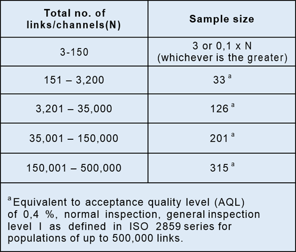
So for an installation of 984 links, you would select 33 victim links.
Selecting a victim link
We can again look to the cabling standards for guidance. For example, in IEC 61935-1 we find:
The disturbed links shall be approximately divided equally between
- links within the group having the highest insertion loss in the installation,
- links within the group having the lowest insertion loss in the installation,
- links within the group having the median insertion loss in the installation.
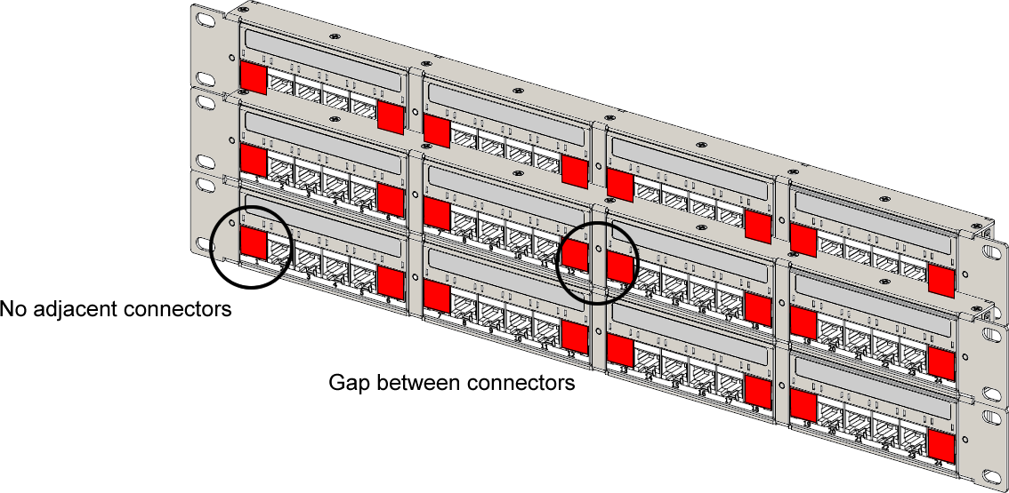
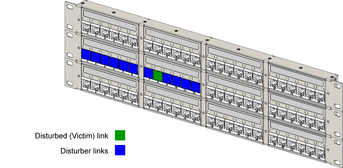
And in ANSI/TIA-568-C.2 we find additional information on the region of influence. Let's take an example. And remember, this is sample testing so we are looking for a worst case situation. Looking at the links marked in red below, these are not considered suitable candidates for being a victim link. Our victim link needs to have adjacent connectors above, below, left and right.
A better choice would be a link which has connectors side by side without gaps. In this example, we picked this link:
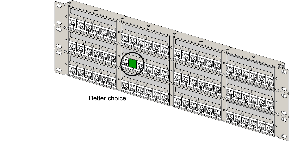
And yes, the three connectors to the right of the connector highlighted in green would also be suitable candidates.
Selecting a disturber links
We can again look to the cabling standards for guidance. For example, in IEC 61935-1 we find:
Disturbing links shall include both of the following:
– all of the links that are in the same cable bundle or the most consistently positioned relative to the disturbed link as disturbing links
– those that occupy adjacent positions to the left, right, above and below connections on the disturbed link on patch panels or multiple outlets
So the smaller your bundle size, the less effort required for alien xtalk testing. Something to consider in your design!
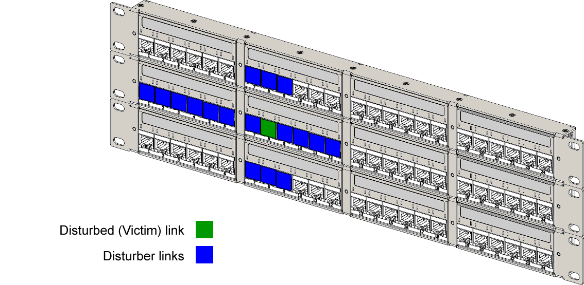
In this example, the bundle size was 12 cables. Which resulted in the following choice for disturbers:
Not forgetting of course the adjacent connectors above and below the victim link:
Now that the victim and disturbers have been identified, it's time to create a LinkWare PC file (.flw) with the Permanent Link or Channel tests for these disturbers and victim links only. So go ahead and open your LinkWare PC file with your Permanent Link or Channel results. Locate your disturbers and victim links. Copy them to a new blank LinkWare PC file. Save that LinkWare PC file using the cable ID of the victim link. Create a LinkWare PC file for each select victim link with their associated disturbers. If you take the time to do this, your testing will go a great deal quicker with less errors.
If you have not done so already, go ahead and download AxTalk Analyzer.
Open AxTalk Analyzer. Click on File > New. You will be prompted to open your LinkWare PC file you created with just your disturbers and victim links. Go ahead and do that. You will then be prompted to select your disturbed (victim) link from the list of cable IDs.
Now let's connect your DSX-5000 CableAnalyzer to begin testing:
Refer to the online help in AxTalk Analyzer for more information.


