Cable Testing 101: But the Standard Says 0.75 dB!
April 18, 2018 / General, 101 learning, Installation and testing, Best Practices
We’ve covered fiber insertion loss testing in depth in many blogs, so by now you should know that it is the loss of signal that happens in a channel due to the length of the cable and any connectors, splices or splitters.
And hopefully you also know that estimating your loss budget involves adding up the loss of all of these components to make sure you’re within the loss limits specified by IEEE standards for the application you plan to run.
There is however one aspect of insertion loss that has appeared to cause some confusion—the fact that TIA standards specify a maximum fiber connector loss of 0.75dB. If the design calls for multiple connection points and this value seems too high for your channel, it’s probably because it is. Let’s take a closer look.
A Limiting Worst-Case Scenario
TIA specifies a maximum value for fiber connectors of 0.75dB because it is considered worst-case scenario. It is therefore rather high and not exactly realistic since most fiber connectors typically have a range of 0.3 to 0.5dB for standard loss and 0.15 to 0.2 for low loss.
If you use the 0.75dB value when estimating the insertion loss for the application you plan to run, as well as any future applications that might run over the same cabling plant, you might think that you either can’t support the application or that you need to eliminate connection points.
For example, 40 Gb/s multimode (40GBASE-SR4) applications have a maximum channel insertion loss of 1.5dB over just 150 meters of OM4. Considering 3.0dB/km for the fiber, an OM4 150-meter length of fiber will be equal to about 0.45dB. That leaves just 1.05dB (1.5dB – 0.45dB) for your connectors. If you use the 0.75dB value for estimating the loss of the connectors into the channel, you would only be able to add one connector into the channel! This wouldn’t even allow for the use of connectors at both end of the channel, preventing the use of interconnects or cross-connects.
Why Add More Connection Points?
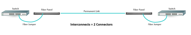
Deploying more connection points to accommodate interconnects or cross-connects at both ends of a channel provides convenient patching areas that can help maintain flexibility and manageability, ease deployments and upgrades, and limit access to critical switches. In an interconnect scenario, fiber panels that mirror switch ports connect via permanent, or fixed, links to fiber panels that mirror switch ports at the other end of the channel. These panels can be located in separate cabinets, which allows the switches to remain untouched and secure. However, including interconnects at both ends adds two additional connection points into the channel.
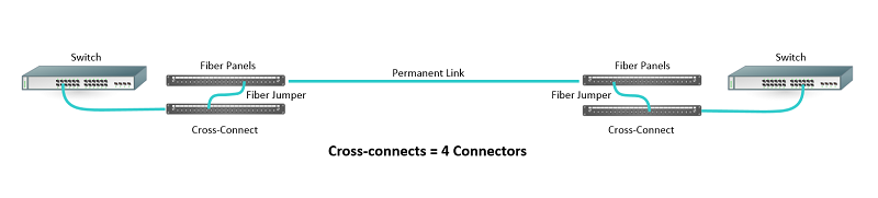
n a cross-connect scenario, two fiber panels located at one end of the channel are connected via fiber jumpers. This creates a patching area where changes can be made by simply repositioning the fiber jumpers between the two panels. And using cross-connects at both ends of the channel creates an “any to all” configuration, whereby any switch port at one end can be connected to any switch port at the other end using just the fiber jumpers at the cross-connects. Each cross-connect adds two connection point into the channel—that’s a total of four connection points if using them at both ends.
Actual Loss Can Get You There
While estimating loss using the TIA maximum value of 0.75dB prevents the use of interconnects or cross-connects at both ends of the channel, that doesn’t necessarily mean you can’t use these configurations. That’s why it’s better to use the actual loss of the connectors you plan to deploy when estimating your loss.
Using the aforementioned 150-meter 40 Gb/s application example that leaves just 1.05dB for your connectors, if your connectors have a low loss of 0.2dB, you would be able to accommodate 5 connections in a channel to support cross-connects at both ends. With a loss of 0.3 dB, you could accommodate 3 connections for a cross-connect at one end and an interconnect at the other. And even if your connectors have a loss of 0.5dB, you could still accommodate interconnects at both ends of the channel. This is one reason why insertion loss performance is a critical parameter when selecting your connectivity—especially if the design calls for multiple connection points.
Given these scenarios, it’s easy to see why you should base your loss estimates on the actual connector loss specified by your connector manufacturer versus the 0.75dB worst-case scenario value called out in the TIA standards.
Regardless of what value you use to estimate your total loss, the only way to really know if you’ve stayed within the insertion loss requirements for the application is to test the channel after installation via Tier 1 testing using an optical loss test set like Fluke Networks’ CertiFiber® Pro.
Publicações recentes Ver tudo >
O que é fibra óptica? Um guia
20-3-2024
O que é perda de retorno?
14-2-2023
Mais publicações gerais Ver tudo >
O que é fibra óptica? Um guia
20-3-2024
Explore nossos Produtos
CertiFiber® Pro Optical Loss Test Set


©2006-2021 Fluke Corporation。保留所有权利。
RM2011, 20/F, SCITECH Tower, 22 Jianguomenwai Avenue, Chaoyang District, Beijing, China
地址:北京市朝阳区建国门外大街22号赛特大厦20层2011室
联系电话:400-8103435
沪ICP备11037028号-15![]()